
High voltage supply

The described circuit utilizes a 6 V battery as the power source, which is capable of generating a high DC voltage in the range of 100-150 Vdc through a center-tapped configuration. This setup is achieved using a 6.3 V transformer that is connected in reverse, allowing for the step-up of voltage. The transformer operates under the principle of electromagnetic induction, where the primary winding is energized by the low voltage from the battery, inducing a higher voltage in the secondary winding.
In this configuration, a transistor is employed as a key component in a Hartley oscillator circuit. The Hartley oscillator is known for its ability to generate high-frequency oscillations, which are fundamental in applications such as RF transmission and signal generation. The frequency of oscillation can be finely tuned by adjusting the resistance value of the 10-ohm resistor in the circuit, allowing for greater flexibility in frequency selection.
Additionally, a 10 µF capacitor is included in the circuit design. This capacitor must be rated for a minimum working voltage of 250 Vdc to ensure reliability and safety during operation. The capacitor plays a crucial role in the timing and stability of the oscillator circuit, affecting the charge and discharge cycles that contribute to the oscillation frequency.
Overall, this electronic schematic represents a compact and efficient design for generating high voltage from a low voltage source while providing adjustable frequency output, suitable for various electronic applications.A 6 V battery can provide 100-150 Vdc center-tapped at a high internal impedance (not dangerous though it can inflict an unpleasant jolt). A 6.3 V transformer is connected ' 'in reverse'' with a transistor used in a Hartley oscillator configuration.
The frequency of operation may be controlled by varying the value of the 10 ohm resistor. The 10 µ¥ capacitor must have a working voltage of at least 250 Vdc.
Related Circuits
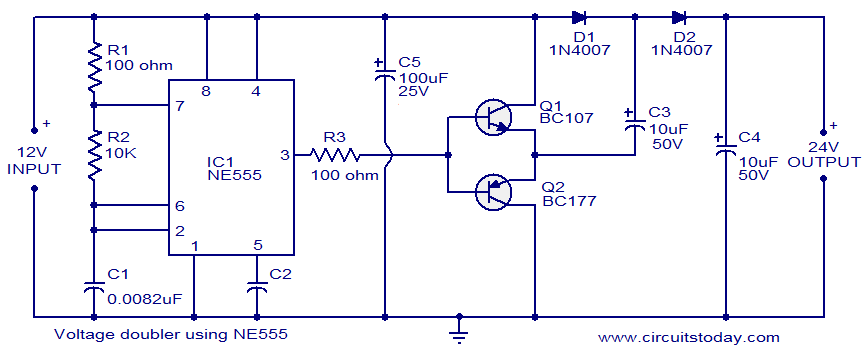
The circuit diagram of a simple voltage doubler using the NE555 timer is presented. In this configuration, the NE555 IC operates as an astable multivibrator at approximately 9 kHz. The bases of two transistors, Q1 and Q2, are connected...
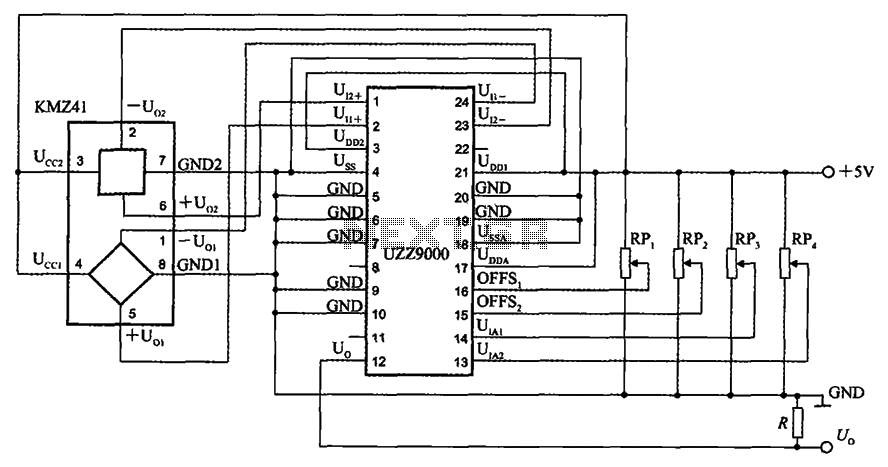
The UZZ9000 KMZ41 detection circuit is configured based on the voltage output type and angle. It operates with a +5V power supply. Potentiometers RP1 and RP2 are used for offset voltage adjustment, while potentiometers RP3 and RP4 are utilized...
This dual polarity power supply is easy to build, requires few parts, and is adjustable from 0-15 volts. It is great for powering op amp circuits, as well as other circuits that require a dual supply voltage. The dual polarity...
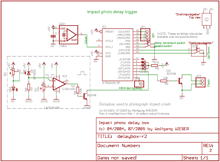
The objective is to capture various stages of a rapid process, especially in comparison to the resolution of the human eye. Due to the lack of advanced equipment such as a high-speed film camera, a practical setup utilizing a...
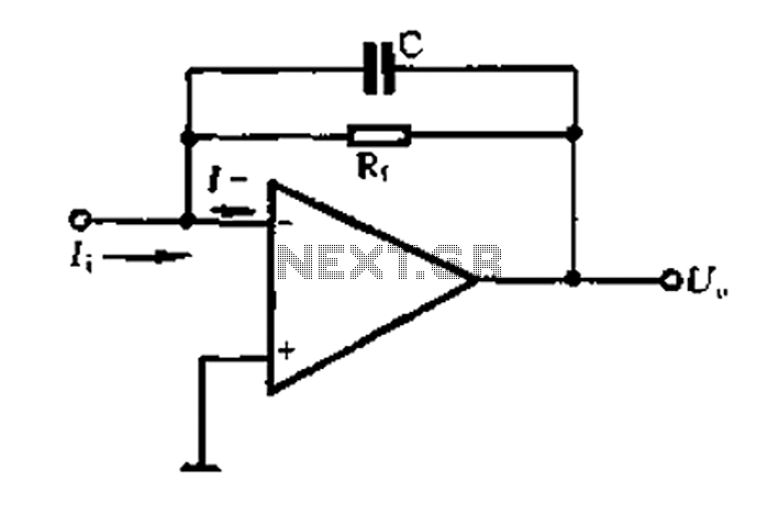
A current-voltage conversion circuit. A current-voltage conversion circuit is designed to transform an input current signal into a corresponding voltage signal. This type of circuit is fundamental in various applications, including sensor interfacing, signal conditioning, and analog-to-digital conversion processes. Typically,...
The purpose of a DC power supply is to deliver the necessary level of DC power to a load by utilizing an AC supply at the input. Various applications demand different specifications; however, contemporary DC power supplies often ensure...