
honda motorcycle cb750f ciruit diagram

The electrical wiring diagram for the Honda Motorcycle CB750F serves as a crucial reference for understanding the intricate connections and functionalities of various components within the motorcycle's electrical system. The diagram provides a visual representation of how each element, including indicator lights, switches, and power sources, interacts within the system.
The right turn signal indicator light and left turn signal indicator light are essential for signaling lane changes and turns to other road users. The oil pressure warning light is a critical safety feature that alerts the rider to low oil pressure, indicating potential engine issues. The neutral indicator light indicates when the transmission is in neutral, allowing for safe starting of the engine.
The diagram includes various switches such as the clutch switch, which ensures the engine can only be started when the clutch is pulled in, and the engine stop switch, which allows the rider to quickly cut off the engine in case of an emergency. The ignition switch controls the power supply to the motorcycle's electrical system, while the fuses protect the wiring from overloads.
The battery serves as the primary power source for the motorcycle's electrical components, while the alternator and regulator/rectifier work together to maintain the battery charge and provide power to the system during operation. The starter motor is responsible for turning the engine over, initiating the combustion process.
Additionally, the diagram outlines the connections for lighting components, including the headlight, tail light, and brake light, ensuring visibility for both the rider and other road users. The presence of the color code within the wiring diagram aids in the identification of wire functions, facilitating troubleshooting and repairs.
Overall, this detailed wiring diagram is an essential tool for technicians and enthusiasts alike, enabling effective maintenance, repair, and modifications to the Honda Motorcycle CB750F's electrical system.The afterward account shows the electrical base affiliation diagram for Honda Motorcycle CB750F. It shows the affiliation amid Honda genitalia such as the appropriate about-face arresting indicator light, oil burden admonishing light, aloof indicator, aerial axle indicator, about-face arresting indicator, tachometer lights, speedometer lights. tur n/signal active lights, headlight, about-face signal/running light, horn and horn button, clamp switch, advanced stop switch, about-face arresting ascendancy switch, dimmer switch, agent stop switch, atom units, aloof switch, oil burden switch, rear stop switch, fuses, agitation switch, amateur motor, battery, about-face arresting appropriate rear, appendage and anchor light, about-face arresting larboard rear, regulator/rectifier, alternator, agitation coils, beating generator, atom plugs, and additionally the blush code. 🔗 External reference
Related Circuits
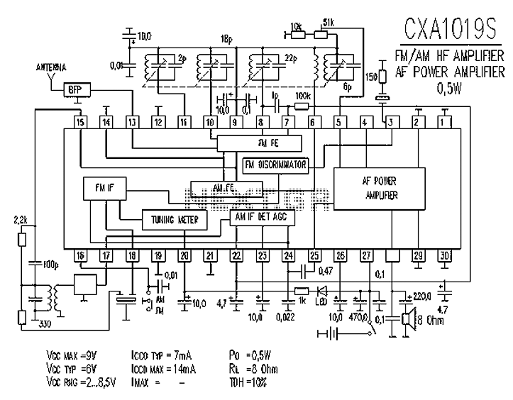
CXA1019 is a high-performance, high-sensitivity FM/AM radio special manifold developed by Sony, Japan. The CXA1019 features high integration, which includes an FM/AM tuner circuit, a mixer circuit, a mute circuit, an amplifier circuit (power output of 0.5 to 1W),...
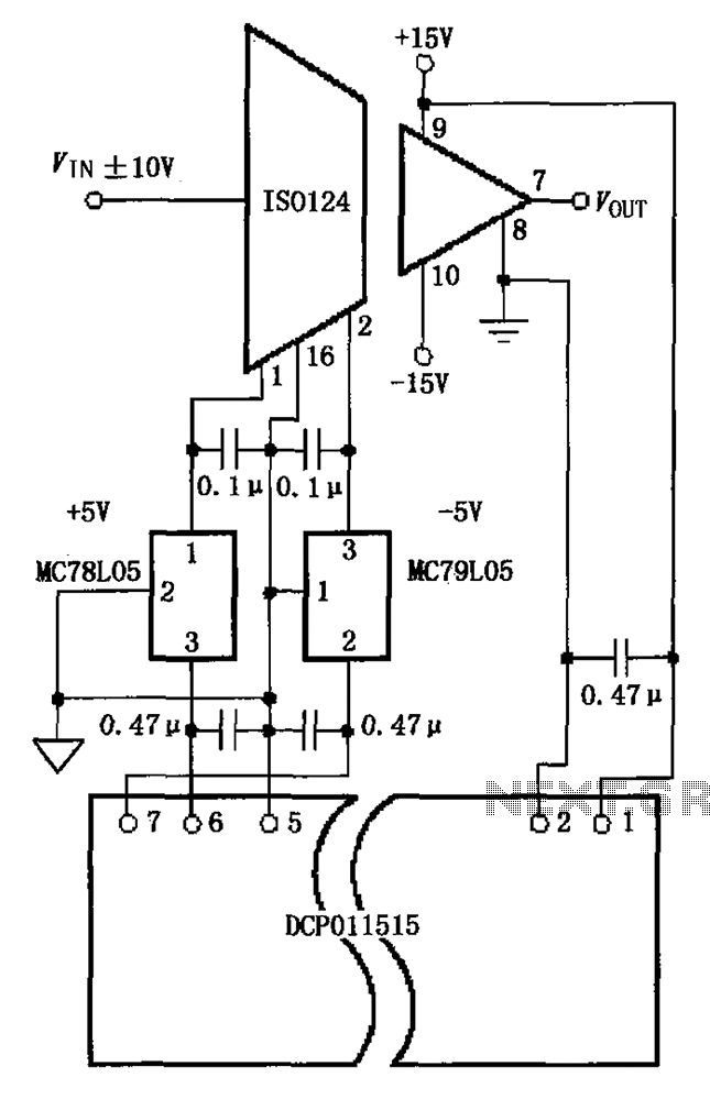
The circuit depicted in the figure includes the ISO124 and MC78L05 components, along with an external regulator, MC79L05, and the DCP011515, which collectively enhance the power supply rejection ratio (PSR) of the circuit. The input signal, VIN (maximum swing...
Learn to interface a 4x4 matrix keypad with AVR and 8051 microcontrollers, and program these microcontrollers in C and assembly language for the keypad matrix. The 4x4 matrix keypad is a popular input device used in various electronic applications, allowing...
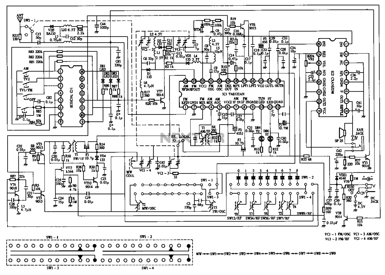
The circuit diagram for the Desheng 119 700 type FM, TV sound, medium wave, and short wave high sensitivity L2-band stereo radio is presented below. The Desheng 119 700 type radio circuit is designed to receive various frequency bands including...
Renewable energy discussions encompass various alternative energy, renewable energy, and free energy technologies. Discussions about environmental issues, global warming, and other related topics are also welcome. It is important to address the validity, organization, and general advice concerning the...
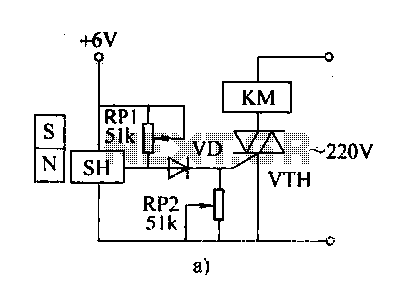
The automatic weapon features a magnetic switch circuit that is simple, reliable, has a low failure rate, and offers good versatility. It can be used for output performance or converted into mechanical displacement applications. The circuit diagram utilizes a...