
How To Build A Sequential Timer Using A Cmos 4017

The circuit design leverages the CMOS 4017 decade counter, which features ten output pins capable of sequentially activating devices based on a clock input. Each output pin can be connected to a different load, allowing for diverse applications such as lighting sequences, sound generation, or relay control. The use of resistors (R1 to R4) ensures that the output current remains within safe limits for the connected devices, while also providing the necessary base current to drive the transistor switch effectively.
The timing aspect of the circuit is crucial for controlling the duration of each event. The capacitor C5 serves as the timing element, with its charge and discharge cycles dictating the length of each output pulse. By selecting appropriate resistor values (R5 to R8) in conjunction with the capacitor, precise timing intervals can be achieved. The initial delay introduced by Q1 discharging C5 can be adjusted by modifying the resistance of R11, thus allowing for greater flexibility in the timing sequence.
For applications requiring longer durations, the choice of larger capacitors or higher resistor values can be implemented, but care must be taken to ensure that the circuit components can handle the increased load and timing requirements. The design is versatile, making it suitable for various electronic projects where sequential control is required.This circuit uses a Cmos 4017 decade counter to create a sequence of four separate events. The number of events in the sequence may be increased to nine or ten. And the length of each event is controlled independently. D13 causes the sequence to repeat continuously. If you leave out D13 - the sequence will run only once. I`ve used a 12-volt supply in the diagram - but the circuit will work at anything from 5 to 15-volts. The four outputs are taken from pins 3, 2, 4 & 7 - in that order. The current available from each output pin is controlled by R1, R2, R3 & R4. Each resistor will supply more than enough current to operate a transistor switch. And the switch can be used to energize a relay - sound a buzzer etc. You`re not limited to a series of - "one after the other" - events. You can produce More Complex Sequences - with overlapping and repeating events. You can also fix the total number of times your sequence will repeat - as well as the point in the sequence where the repetition will stop. The individual output times are controlled by the value of C5 - and the values of R5, R6, R7 & R8 respectively.
At the beginning of each event - Q1 discharges C5. Then the relevant timing resistor takes over - and charges C5 up again. I used a 470uF capacitor in the prototype. And with the resistor values shown in the diagram - the events lasted 38 seconds, 67 seconds, 49 seconds and 9 minutes - respectively. These times each include an initial delay of about 14 seconds - while Q1 discharges C5. Until Q1 switches off - the timing resistors cannot begin to charge C5. Manufacturing tolerances mean that your results are likely to be different from mine. However - because you`re always using the same capacitor to activate the same input pin - the length of each step in your sequence should be fairly predictable.
All you need is one reliable practical observation. Then you can calculate the rest. I got roughly 12 seconds for every 100k/100uF combination. So a 1M resistor and a 100uF capacitor will give about 120 seconds - or two minutes. To this must be added the initial 14 seconds - while Q1 discharges C5. If you want to shorten this discharge time - reduce the value of R11. There`s no theoretical limit on the size of C5. With the 470uF capacitor and the 1M resistor I got just under 9 minutes. So - with a 4700uF capacitor - the 1M resistor should give me just under 90 minutes. And if I increase the resistor to 4M7 - the output should last for around 7 hours. 🔗 External reference
Related Circuits
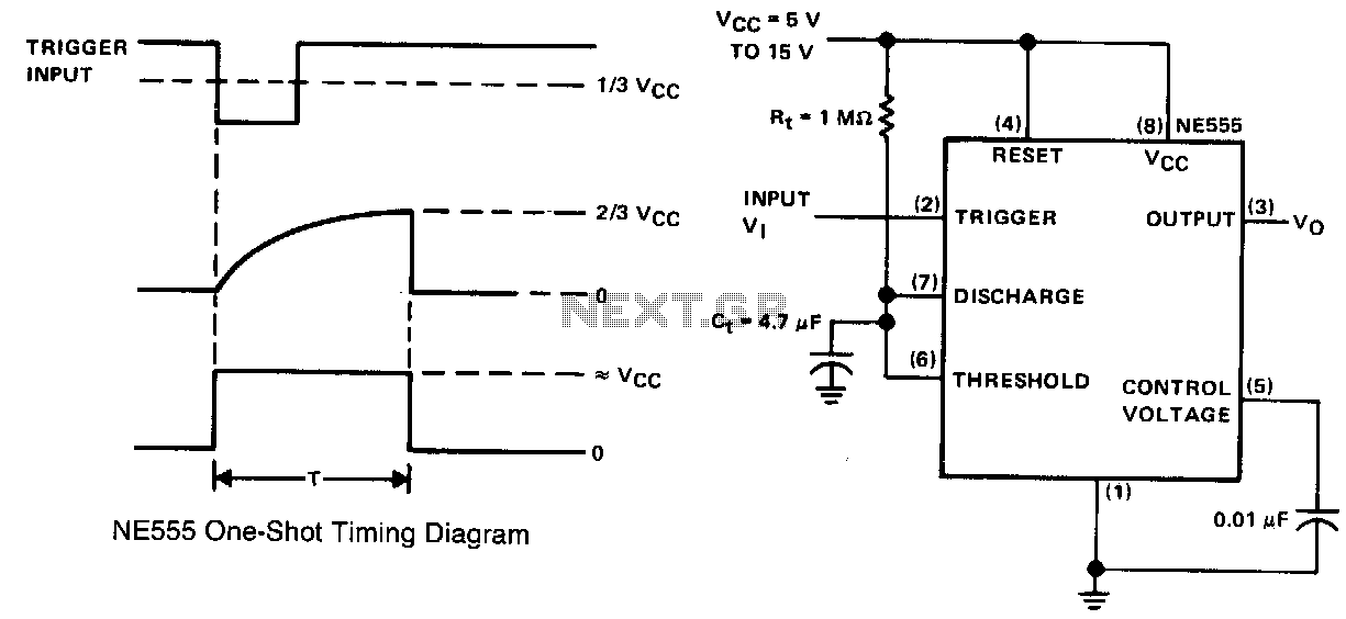
This simple circuit consists of only two timing components, Rr and Cr, the NE555 timer, and a bypass capacitor C2. Although C2 is not essential for operation, it is recommended for noise immunity. During standby, the trigger input terminal...
This guide provides instructions for becoming a radio pirate by creating a low-power FM transmitter to broadcast content on the airwaves. It serves as a follow-up to a recent call for easing restrictions on radio broadcasting in the Maldives....
If EAGLE is not available, a full working version can be downloaded from CadSoftUSA. A zip file containing the EAGLE schematics is provided. The EAGLE software is a widely used electronic design automation (EDA) tool that facilitates the creation of...
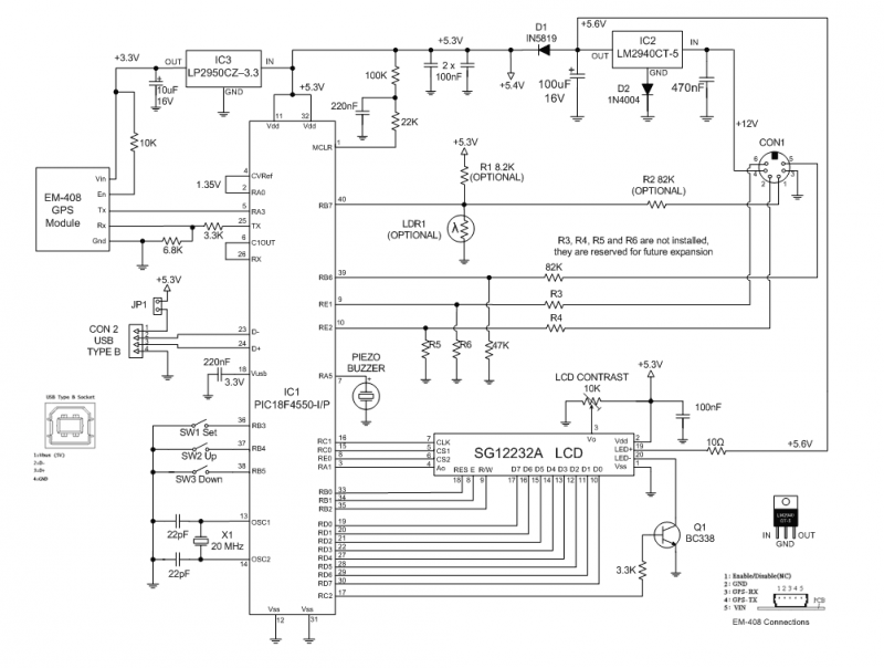
The GPS Car or Boat Computer is capable of displaying a variety of GPS-related information for enthusiasts of driving or boating. This page contains all the necessary information to construct the unit, including design specifications, schematic diagrams, parts list,...
It is very interesting and convenient to be able to control everything while sitting at your PC terminal. Here, a simple hardware circuit and software is used to interface a 7-segment based rolling display. The printer port of a...
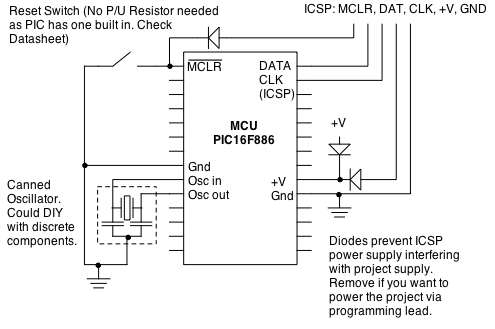
Microcontrollers (MCUs) are versatile integrated circuits (ICs) that enhance the functionality of electronics, robotics, and various other projects. Microcontrollers serve as the brain of embedded systems, providing control, processing, and communication capabilities in a compact form factor. They typically consist...