
How to implement a soft power switch controllable by microcontroller

The described circuit involves a microcontroller that manages power states through a GPIO pin and a momentary pushbutton. The circuit operates in a low-power state, where the microcontroller and other components are deactivated to conserve energy. When the user presses the momentary button, the battery voltage is applied to the -SHDN pin, which activates the voltage regulator, supplying 3.3V to the microcontroller.
Once powered, the microcontroller immediately sets the POWER ON pin high, ensuring that the system remains powered even after the button is released. This design prevents unintended shutdowns due to button release. When the microcontroller determines it is necessary to shut down, it drives the POWER ON pin low, effectively turning off the power to the system.
To address concerns regarding switch bounce, which can cause multiple transitions when the button is pressed, it is advisable to implement a capacitor on the -SHDN pin. This capacitor creates a time constant that smooths the voltage transition, ensuring stable activation of the regulator. A capacitor value of 10 nF is often recommended for noise suppression, as indicated in typical datasheet schematics.
Additionally, it is crucial to ensure that the microcontroller only attempts to power on the system when its supply voltage (VDD) is above the threshold necessary for reliable operation. This precaution prevents the microcontroller from executing unpredictable code when VDD is insufficient, which could inadvertently set the POWER ON lead high and cause erratic behavior. Proper design considerations should include monitoring VDD levels and implementing appropriate logic to manage power states effectively.A circuit such that the microcontroller can toggle a GPIO pin and shut the whole system (including microcontroller itself) down. And when the user presses a momentary button, the power is brought back up again. The circuit is normally powered down. When the user presses the pushbutton, the battery is fed into the -SHDN pin, enabling the regulator and turning
on the 3. 3V to the microcontroller. The microcontroller then puts a logic 1 on the POWER ON lead, holding the power on after the user releases the pushbutton. When the microcontroller wants to shut itself off, it sets the POWER ON lead to 0. @Kortuk, good point. I was assuming the micro would turn on fast enough that it could override the switch before the first bounce, assuming driving the pin high was the first thing the micro did.
If that isn`t the case, one could add a capacitor on the -SHDN lead to create a time constant for the turn on (although this would also introduce a slight delay in turn off). The 10 nF one probably needs to be left in for noise suppression (it was included in a datasheet sample schematic).
Or one could add additional RC circuit for just the switch. tcrosley Jan 14 `11 at 16:36 A bigger issue that switch bounce is processor behavior during power-down. In particular, it may be good to make sure that the processor can only turn the supply on when its VDD is above the point where correct operation is guaranteed.
I`ve had to tweak some auto-power-down circuits that would occasionally fail as a consequence of the processor running random code when VDD fell below the valid operating voltage. The random code could set the "power on" output high, which would in turn power the device back up, running code at a random address.
supercat May 30 `11 at 1:45 🔗 External reference
Related Circuits
All files are found using legitimate search engine techniques. This site does not condone hacking into sites to create the links it lists. It is assumed that all links found on the search engines used are obtained legally and...
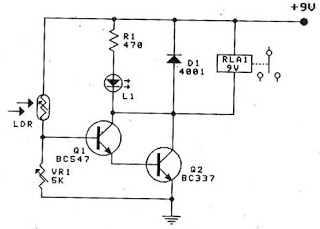
A collection of touch switch circuits is presented. A touch switch is an electronic device that allows control of a circuit simply by touching a sensor. The circuit diagram illustrates a simple design that utilizes only eight components. The...
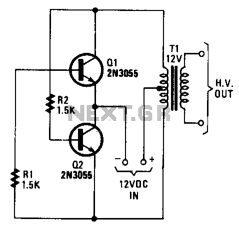
The transformer can be any 6.3 or 12.6 V type. Apply the 12-V DC input so the positive goes to the transformer's center tap and the negative goes to the two transistor emitters. Any bridge-type rectifier and filter can...
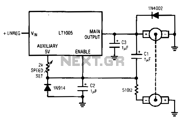
This circuit utilizes a tachometer to generate a feedback signal that is compared to a reference provided by the auxiliary output. Upon power application, the tachometer output is initially zero, allowing the regulator output to activate and supply current...

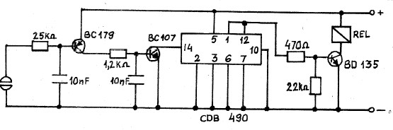
In the design of microcontroller-based electronic projects, the use of a Reset IC is critical for applications that require the microcontroller (MCU) to operate only at its optimum voltage. Without reset circuitry, the MCU may enter a tristate condition,...
Speaker relay delay controlling circuit for audio amplifier The speaker relay delay controlling circuit is designed to manage the connection of speakers to an audio amplifier, ensuring that the speakers are activated only after a specified delay. This delay serves...