
hv neon lamp multivibrator

The high voltage required for this circuit can be supplied by batteries or, alternatively, a high voltage DC to DC converter may be employed for cost-effectiveness and convenience. The oscillator operates at a fixed frequency, which is determined by the two resistors (R1 and R2), the capacitor (C1), and the ionization voltages of the selected neon lamps. If R1 and R2 are identical, the output waveform will approximate a square wave with a near 50% duty cycle; otherwise, the duty cycle will vary. Through experimentation, the desired frequency can be easily adjusted. Selecting a low frequency will cause the lights to blink alternately, resulting in a blinking light effect. The output drive of this oscillator is somewhat limited, and it is recommended to use a separate amplifier stage to utilize the available output signal effectively; otherwise, the frequency may be impacted. A single vacuum tube or solid-state amplifier is ideal for isolating the oscillator frequency from unwanted feedback changes.
Parts and materials include:
- B1: Battery, 80 Volt
- C1: Capacitor, 0.1 µF, 50V, Disc
- C2: Capacitor, 0.01 µF, 150V, Disc or Film
- NE1, NE2: Neon Lamp, Type NE2 or similar
- R1, R2: Resistor, 1K, 5%, 1/4W, CC
This circuit operates on the principle of a relaxation oscillator, where the neon lamps serve as the active switching elements. Upon reaching the ionization voltage, the neon lamps will conduct, allowing current to flow through the resistors and charging the capacitor. As the capacitor charges, the voltage across it rises until it reaches the threshold to extinguish the neon lamps, at which point the cycle repeats. The timing characteristics of the circuit can be modified by varying the resistor values and capacitor size, allowing for a range of operational frequencies. The choice of neon lamp type can also influence the performance, particularly in terms of the ionization voltage and the resulting blinking frequency.
To ensure stable operation and to minimize the influence of external factors, it is advisable to place the oscillator in a controlled environment, away from electromagnetic interference. The circuit's simplicity and reliance on passive components make it an excellent educational tool for understanding basic oscillator principles and the behavior of neon lamps in electronic circuits.This unusual, simple multi-vibrator has only five components and uses neither vacuum tubes nor semiconductors but two miniature NE2 type neon lamps. This circuit interfaces best with vacuum tube or FET type high-impedance circuits. Almost any type of neon bulbs would work fine in this circuit not just the NE2 type but they have to be in their own separate glass envelope.
The high voltage to operate this circuit may be supplied by batteries or it may be less expensive and more convenient to use a high voltage DC to DC converter. This oscillator has a fix frequency that is determined by the two resistors R1 and R2, capacitor C1 and the ionization voltages of the types of neon lamps.
If the two resistors are identical than the output waveform would be nearly squarewave - a wave with a near 50% duty cycle, otherwise the duty cycle will more or less than 50%. With a bit of experimentation the required frequency could be easily set up as required. When a low frequency is selected the lights blink on and off alternating and the circuit provides a blinking light.
The output drive available from this oscillator is rather limited. The available output signal can best be utilized driving a separate amplifier stage; otherwise the frequency would be affected. A single vacuum tube or solid state amplifier is the best for isolating the oscillator frequency from unwanted outside caused feedback changes.
Parts and materials: B1 - Battery, 80 Volt C1 - Capacitor 0. 1 uF, 50V, Disc C2 - Capacitor 0. 01 uF, 150V, Disc or Film NE1, NE2 - Neon Lamp, Type NE2 or similar R1, R2 - Resistor 1K, 5%, 1/4W, CC 🔗 External reference
Related Circuits
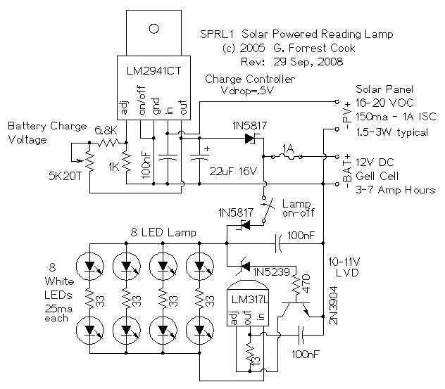
The reading lamp consists of a small solar panel, a standard UPS style lead acid battery, and an LED circuit board. The circuit board contains a low power solar charge controller (regulator), a set of 8 white LEDs, a...
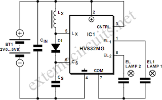
An EL lamp is a solid-state, low-power, uniform area light source. Due to its thin profile (as thin as 0.3 mm) and its capability to be manufactured in various sizes and shapes, EL lamps serve as an ideal solution...
According to current legislation in many countries, vintage cars must also be fitted with a rear fog lamp. Modern vehicles incorporate circuitry associated with the fog lamp switch to prevent the fog lamp from activating when the lights are...
The UBA2021 can be utilized as a 600 V lamp controller and half-bridge driver integrated circuit (IC) for high-power applications. It is designed for long-life compact fluorescent lamp (CFL) and tubular fluorescent lamp (TL) applications. The UBA2021 is a versatile...
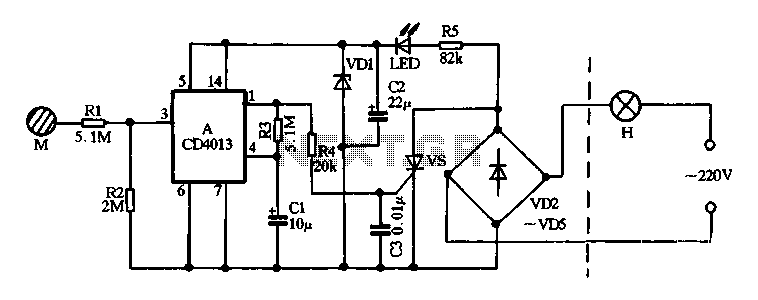
Diodes VD2 to VD5 and SCR form the main circuit of a touch switch. Resistor R5 and diode VD1 create a power supply circuit that outputs approximately 12V DC, which is utilized for a manifold A application. The circuit...

This circuit is a 220V AC lamp touch dimmer. By simply touching the dimmer, the light intensity of incandescent lamps can be increased in three stages. The touch dimmer is primarily based on an 8-pin CMOS IC, specifically the...