
Hyper-Simple Battery Capacity Tester

The described circuit utilizes a simple yet effective method to gauge battery capacity by leveraging a standard electric clock and a fixed resistor. The resistor serves to increase the discharge rate of the battery, allowing for a more accurate assessment of the battery's remaining energy. The choice of a 5.6-ohm resistor is critical, as it generates a steady discharge current of approximately 214 mA when connected to a 1.2 V battery. This current level is significant for providing a reliable estimate of the battery's capacity in milliampere-hours (mAh).
To implement this circuit, the battery terminals are connected to the electric clock, while the resistor is placed in parallel with the battery. The clock's operation time can be easily monitored, and by calculating the total discharge (current multiplied by time), one can derive the battery's capacity. It is important to note that for NiCd batteries, the discharge process must be carefully managed. These batteries are sensitive to over-discharge, which can lead to irreversible damage. Hence, a multimeter is recommended to be connected in parallel with the resistor to continuously monitor the battery voltage during the discharge process. This precaution helps ensure that the battery is removed from the circuit before it reaches a dangerously low voltage, thus preserving its longevity and performance.
In summary, this circuit offers a practical solution for assessing battery capacity while emphasizing the importance of careful monitoring, particularly when working with NiCd batteries. The integration of a multimeter for voltage monitoring enhances the safety and reliability of the discharge process, making it an effective tool for battery management.The circuit described here is eminently suitable to indicate the capacity of a battery. We use a cheap electric clock for this. By connecting a resistor across the battery terminals, the battery is discharged somewhat faster than with the clock alone. If we pick a resistor with a value of 5. 6R, the discharge current amounts to 1. 2 V / 5. 6 R = 214 mA. If we multiply this with the number of hours that the clock ran after the battery was connected up then we know (approximately) the capacity of the battery. When discharging a NiCd battery we need to make sure we remove the battery the moment the clock stops running.
NiCd batteries do not tolerate too deep a discharge very well. We therefore recommend keeping an eye on the voltage in one way or another, for example by connecting a multimeter in parallel with the resistor. 🔗 External reference
Related Circuits
This simple device checks if there is water in a pot plant. You stick the two probes (paperclips) into the pot plant and if the LED lights, it means there is water in the pot plant. The described device operates...
This continuity tester circuit allows for the examination of PCB track failures without the need to visually inspect the routing of the tracks, which can often be frustrating. The continuity tester circuit is designed to facilitate the detection of faults...
A constant-voltage active load can function as a battery during the charge cycle. The load voltage can be adjusted from 5 to 35V using potentiometer PV, simulating batteries with voltages ranging from 6 to 32V. In the testing of...
This tester is designed for tracing wiring on Printed Circuit Boards (PCBs). Resistors below 50 ohms function as a short circuit, while those above 100 ohms behave as an open circuit. The circuit comprises a simple multivibrator activated by...
To build a stepper motor tester, the circuit includes two sets of drivers that support both unipolar and bipolar stepper motors. The control circuit and driver circuit are powered by separate supplies, allowing compatibility with a wider range of...
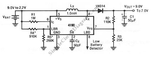
A standard 9V battery is considered depleted when its voltage drops below 7 volts. This switching regulator can extend the lifetime of a 9V battery. The circuit utilizes a switching regulator to optimize the energy usage of a standard 9V battery,...