
Improved Infrared Detector Circuit

The infrared detector circuit is engineered to respond to signals emitted by infrared remote control devices, commonly used in consumer electronics. The core component of the circuit typically includes a photodiode or phototransistor, which detects infrared light. When an IR signal is transmitted from a remote control, the detector converts the light into an electrical signal.
To optimize the circuit's performance, it may integrate additional components such as operational amplifiers to amplify the received signal, filters to eliminate noise, and comparators to establish a threshold for signal detection. A microcontroller can also be incorporated to process the signal further, allowing for more complex functionalities such as decoding specific commands or interfacing with other electronic systems.
Power supply considerations are crucial for the circuit's operation. A stable voltage source, often from a battery or regulated power supply, ensures consistent performance. The circuit may also include power management features to minimize energy consumption, particularly important in battery-operated devices.
The physical layout of the circuit should ensure that the photodetector is positioned to have a clear line of sight to the remote control, maximizing its sensitivity and range. Additionally, the circuit design should account for environmental factors, such as ambient light interference, which could affect performance.
Overall, this infrared detector circuit represents a versatile solution for integrating remote control capabilities into various electronic devices, enhancing user experience and functionality.This improved infrared detector is specifically intended for use with commercial IR remote control handsets. This little circuit is useful for quick go/no-.. 🔗 External reference
Related Circuits
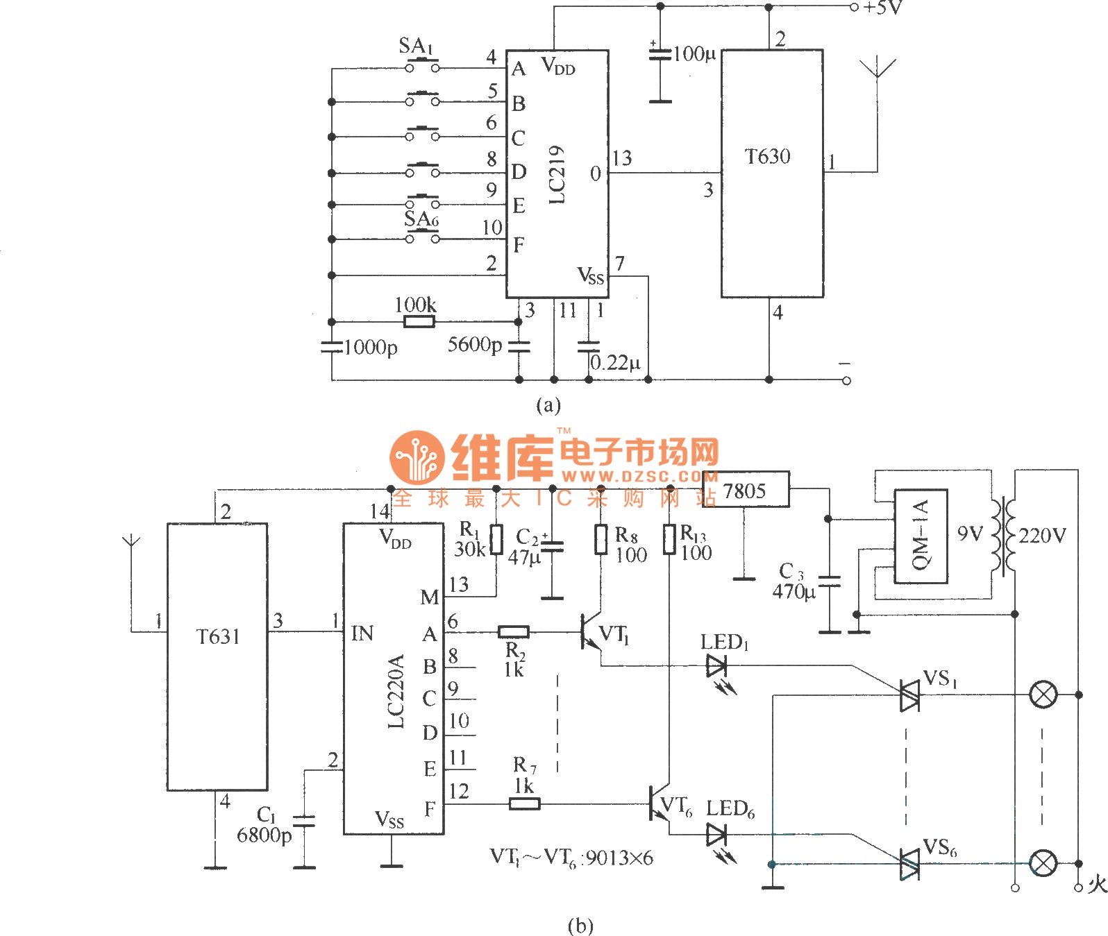
The circuit utilizes the long-wave wireless transceiver T630/T631 to manage a 6-channel load. It is characterized by low power consumption, high resistance to interference, and a simple structure. The circuit design incorporates the T630/T631 transceiver, which operates in the long-wave...
Figure 15-22 illustrates a doorbell system that consists of a monostable timing circuit, a password switch, a NAND gate circuit, and a sound output circuit. The operation of the circuit is designed such that when the password switch is...
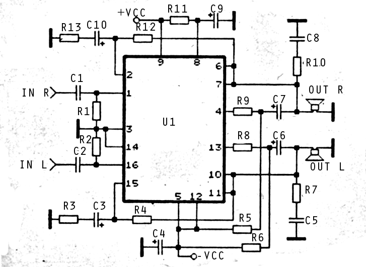
The audio amplifier circuit is highly suitable for home use, particularly with subwoofer or woofer speakers. Commonly referred to as a home amplifier, these audio amplifiers are based on integrated circuits (ICs), specifically the STK series, which includes models...
A request for a DIY 300BSE power amplifier schematic is made, with a specification to utilize Lowther PM6 speakers. The 300BSE power amplifier is a well-regarded audio amplification circuit known for its warm sound and high fidelity, particularly suited for...
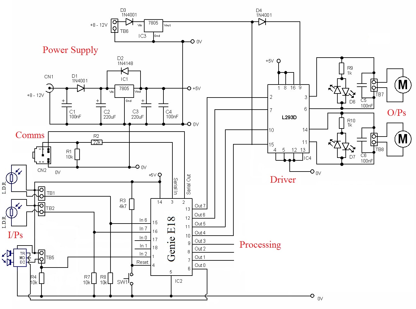
The circuit requires a power source to function. The PIC needs a 5-volt supply, while the driver demands a higher voltage to operate the motors. Inputs: The inputs come from three sensors. Two of these sensors are Light Dependent...
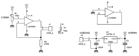
This led tester uses a power switched op-amp. The control range is about 0-30mA. Thus, all test and standard LEDs, the voltage across the LED to read. The power supply is an example lab power supply at least 15V,...