
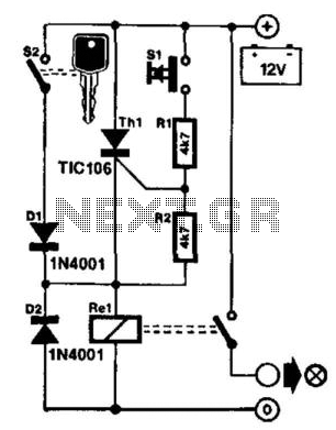
Infared Remote Control Transmitter-Receiver

The schematic for the infrared remote control system consists of two main components: the transmitter and the receiver. The transmitter section includes an infrared LED, which is responsible for emitting modulated infrared light. This modulation corresponds to a specific tone or signal pattern, typically generated by a microcontroller or a simple oscillator circuit. The infrared LED is connected to a current-limiting resistor to ensure it operates within its specified current range, preventing damage from excessive current.
The modulation frequency is crucial for the operation of the system, as it defines the tone that the receiver will recognize. Common modulation frequencies for infrared remote controls are in the range of 30 kHz to 40 kHz, which helps to minimize interference from ambient light sources.
On the receiver side, a photodiode or phototransistor is utilized to detect the incoming infrared signal. This component is sensitive to the modulated light emitted by the transmitter. The output of the photodiode is typically fed into a bandpass filter that isolates the modulation frequency, allowing only the desired tone to pass through. This filtering process is essential for ensuring that the receiver only activates in response to the specific signal from the transmitter, thereby preventing accidental activations due to stray infrared signals.
The filtered signal is then processed by a decoder circuit, which is often implemented using a microcontroller or a dedicated IC designed for infrared signal decoding. The decoder interprets the modulated signal and generates a corresponding output, which can control various devices, such as TVs, air conditioners, or other consumer electronics.
Overall, the infrared remote control system is an efficient and reliable method for wireless communication, characterized by its simplicity and immunity to accidental activations, due to the specific tone detection mechanism employed in the receiver.Here`s schematics for infared remotes. This remote transmits a tone using an infared LED. This tone is decoded by the receiver. Since the receiver only switches when it "hears" the tone, there are no accidental activations. 🔗 External reference
Related Circuits
80 kW resistance salt bath furnace control circuit. The salt bath resistance furnace is a high-power device that employs fast start and temperature control technology to significantly save energy. The circuit includes a single-junction transistor (VTi) used as a...

Useful for A/B control, the IR receiver shown controls a relay from an infrared beam that has a pulsed tone-modulated signal. Q1 is the photo receptor feeding op amp IC1, tone decoder IC2, and flip-flop IC3. IC5 turns off...

Individuals seeking a distinctive gift for Christmas and New Year may find this project appealing. Certification of this project will undoubtedly create a preference for it. The project in question appears to be a creative endeavor aimed at providing a...

This is a versatile Low-Frequency Oscillator (LFO) designed for various modulation applications. The frequency of the LFO can be controlled by voltage, enhancing the range of sound possibilities. The pulse width of the rectangular wave can be adjusted between...
It is frustrating to discover that the car headlights have been left on, resulting in a dead battery. One solution to this problem is the proposed control circuit. This circuit does not issue a warning; instead, it takes action:...
As the only electronics engineer in the family and circle of friends, it is sometimes not possible to avoid requests for assistance. Recently, a request was made by an elderly lady residing in a retirement home. In her room,...