
Infrared Proximity Detector Alarm

The circuit in question is designed to utilize common electronic components, making it an ideal project for hobbyists and engineers looking for cost-effective solutions. The specified resistance value of 22 ohms suggests that the circuit may involve a resistor used for current limiting or voltage division.
To elaborate, the circuit could potentially be a simple LED driver or a basic amplifier configuration. In the case of an LED driver, the 22-ohm resistor would be connected in series with the LED to limit the current flowing through it, ensuring that the LED operates within its safe current rating. This configuration is essential for prolonging the lifespan of the LED and preventing thermal runaway.
If the circuit is intended as an amplifier, the 22-ohm resistor could serve as part of a feedback loop or load resistor in a transistor amplifier setup. In this scenario, the resistor helps define the gain of the amplifier and stabilizes the operation of the transistor by providing a reference point for the input signal.
The overall schematic would typically include a power supply, the 22-ohm resistor, and other components such as capacitors, transistors, or diodes, depending on the specific application. The layout should ensure minimal interference and optimal performance, with careful consideration of the connections and orientation of polarized components.
By leveraging low-cost and readily available components, this circuit exemplifies the principles of electronics design, emphasizing practicality and accessibility for a wide range of users.This circuit can be built from readily available low-cost components, some of which may even be hiding in your junkbox! The indicated value of 22 ? for re.. 🔗 External reference
Related Circuits

This alarm siren circuit produces a continuous frequency sweep, resulting in a warbling sound. The duration of the warbling is approximately 6 seconds, with 3 seconds allocated for frequency sweeping upward and 3 seconds for sweeping downward. The alarm siren...
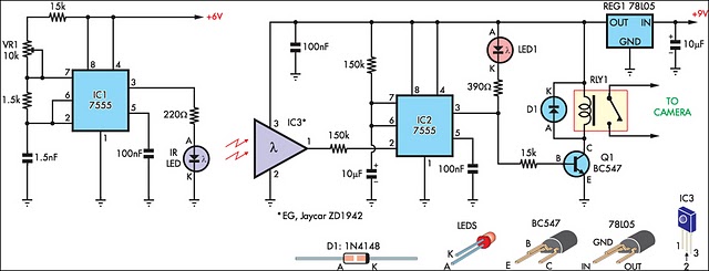
The IR detector (IC3) controls an LM 7555 CMOS timer (IC2) operating in monostable mode. When the beam is interrupted, IC2 is triggered, causing its pin 3 output to go high for approximately half a second. This action turns...
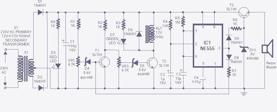
The high and low voltage cut-off with delay and alarm circuit, along with its circuit diagram, is explained in this post. The high and low voltage cut-off circuit is designed to protect electrical devices from damage caused by excessive voltage...
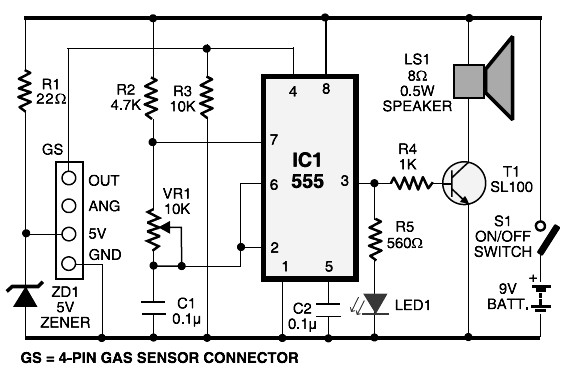
This schematic diagram represents an LPG gas leakage sensor alarm circuit powered by a 9V PP3 battery. A Zener diode (ZD1) is utilized to convert the 9V input into 5V DC, which is required to operate the gas sensor...

A simple alarm circuit with a diagram and schematic that generates a multi-tone sound. This alarm circuit is suitable for use in burglar alarms and sirens and is designed using dual op-amps MC1458 and LM380. The described alarm circuit utilizes...
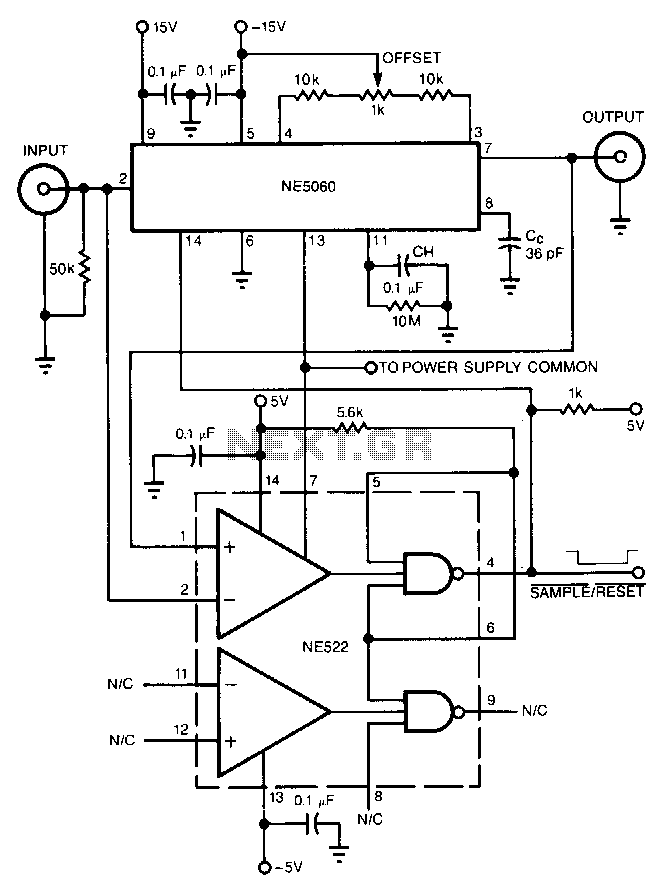
The high-speed peak detector utilizes a highly accurate, fast sample-and-hold (s/h) amplifier that is controlled by a high-speed comparator. The s/h amplifier retains the peak voltage until the comparator switches the amplifier to its sample mode to capture a...