Infrared Remote Control ( 555 / 4013 / 4093 )

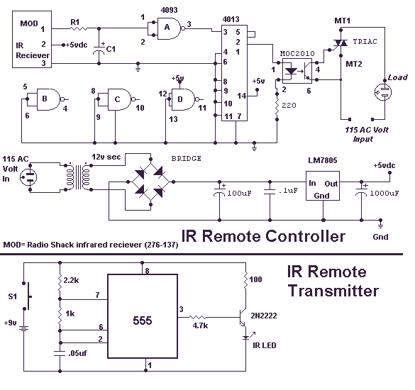
This circuit will allow you to turn on any piece of equipment that operates on 115 volts AC. The receiver circuit is based on the Radio Shack infrared receiver module (MOD), part number 276-137. It is also available from some of the other sources listed on my Links page. The MOD accepts a 40 kHz IR signal that is modulated at 4 kHz. When a signal is received, the MOD will go low. The sensitivity of the MOD is set by different values for R1 and C1. The values for R1 may need to be as high as 10,000 ohms and for C1 40 µF. This will prevent the unit from turning on under normal lighting conditions. You will need to experiment with the values that work best for you. The output of the 4013 chip, a flip-flop, toggles on and off with the reception of an IR pulse. The output of the 4013 turns on the MOC optical coupler, which in turn switches on the triac and supplies power to the AC load.
The described circuit functions as a remote-controlled switch for devices operating on 115 volts AC. The core of the circuit is the Radio Shack infrared receiver module (MOD), which is designed to detect infrared signals modulated at a specific frequency. The receiver is tuned to respond to a 40 kHz signal that is further modulated at 4 kHz, ensuring that it only activates in response to the correct signal, thereby minimizing false triggering from ambient light sources.
The sensitivity of the MOD is adjustable via the resistor (R1) and capacitor (C1) values. R1, which can be set to a maximum of 10,000 ohms, and C1, which should be around 40 µF, form a low-pass filter that helps to eliminate interference from other light sources. Adjusting these components allows the user to find the optimal sensitivity for their environment, ensuring reliable operation.
Upon receiving the correct infrared signal, the MOD outputs a low signal that is fed into a flip-flop circuit composed of the 4013 chip. This flip-flop toggles its output state with each received pulse, providing a binary output that can be used to control other components in the circuit. The output from the 4013 chip is connected to a MOC optical coupler, which serves as an interface between the low-voltage control circuit and the high-voltage AC load.
The MOC optical coupler isolates the low-voltage control circuit from the high-voltage AC circuit, providing safety and preventing potential damage to the control components. When activated by the 4013 output, the optical coupler triggers a triac, which is a semiconductor device capable of switching high AC loads. The triac, once turned on, allows current to flow to the connected AC device, effectively powering it on.
This circuit design is versatile and can be adapted for various applications where remote control of AC devices is required. It is essential to ensure that all components are rated for the appropriate voltages and currents to maintain safety and functionality. Proper heat sinking for the triac may be necessary depending on the load's power requirements, and adequate precautions should be taken when working with AC mains voltage.This circuit will allow you to turn on any piece of equipment that operates on 115 volts ac. The receiver circuit is based on the Radio Shack infrared receiver module (MOD), part number 276-137. It is also available from some of the other sources listed on my Links page. The MOD accepts a 40khz IR signal that is modulated at 4 khz. When a signal is received the MOD will go low. The sensitivity of the MOD is set by different values for R1 and C1. The values for R1 may need to be as high as 10,000 ohms and for C1 40uf. This will prevent the unit from turning on under normal lighting conditions. You will need to experiment with the values that work best for you. The output of the 4013 chip a flip flop toggles on and off with the reception of a IR pulse. The output of the 4013 turns on the MOC optical coupler which in turn switches on the triac and supplies power to the AC load.
🔗 External reference


