
interface keypad with pic12f675

The interfacing of a keypad with the PIC12F675 microcontroller involves several key components and steps to ensure proper functionality. The PIC12F675 is an 8-bit microcontroller from Microchip Technology, featuring a 10-bit ADC, a 12-bit instruction set, and various I/O pins that can be utilized for interfacing with external devices like keypads.
To begin, the keypad matrix layout must be understood. A typical 4x4 keypad consists of 16 keys arranged in 4 rows and 4 columns. Each key press connects a specific row and column, which can be detected by the microcontroller. The interfacing method involves configuring the microcontroller's GPIO (General Purpose Input/Output) pins to read the state of the keypad.
In the schematic, the rows of the keypad are connected to designated GPIO pins configured as outputs, while the columns are connected to GPIO pins configured as inputs. When a key is pressed, the corresponding row pin is driven low, allowing the microcontroller to detect which key was pressed by reading the input states of the column pins.
The code written in C language for the PIC12F675 typically includes initialization routines for configuring the GPIO pins, setting up the ADC if necessary, and implementing a scanning algorithm to detect key presses. The scanning algorithm involves setting each row pin low in succession and reading the state of the column pins. If a column pin reads low while a row pin is set low, it indicates that the corresponding key is pressed.
Debouncing techniques may also be implemented in the code to ensure that multiple signals are not falsely registered due to mechanical bounce when a key is pressed or released. This can be achieved through software delays or by using additional hardware components.
Overall, the interfacing of a keypad with the PIC12F675 microcontroller is a straightforward process that allows for user input in various applications, such as access control systems, user interfaces, and embedded systems. Properly designed schematics and well-structured code are essential for achieving reliable performance in such applications.This post provides a simple method to interface any keypad (e-g 4x4 or 4x3 etc) with PIC12F675 microcontroller. The code for PIC12F675 is written in C lang.. 🔗 External reference
Related Circuits
This is an improved version of the audio interface commonly used to connect a computer soundcard to a transceiver's receive and transmit audio circuits. This kind of interface is used by computer programs that send and receive SSTV, RTTY,...

I have been participating in CW contests using my K2 and N3FJP's logging software. With my modern rig featuring computer control, I aimed to connect it to my old ThinkPad, utilizing the serial port for rig control and the...
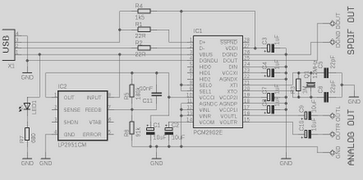
This is a high-quality preamplifier circuit with a built-in USB DAC designed for the Leachamp power amplifier. The schematic is derived from the PCM2902 datasheet. The circuit includes a DAC and ADC, SPDIF output and input, and an HID...
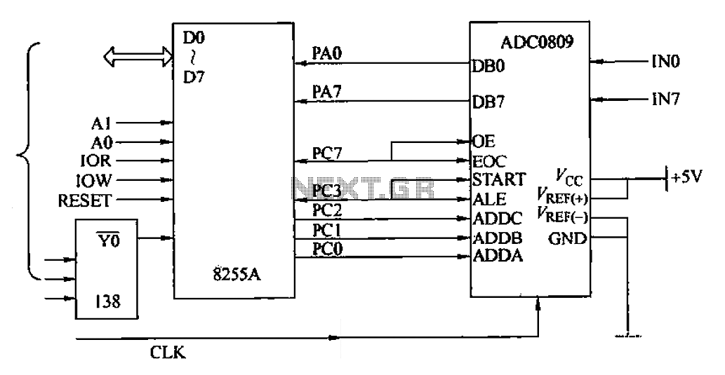
The ADC0809 is an 8-channel analog switch integrated with an 8-bit successive approximation analog-to-digital (A/D) converter. It supports the selection of eight input channels through address latch and encoder channel selection signals ADDA, ADDB, and ADDC. The address latch...
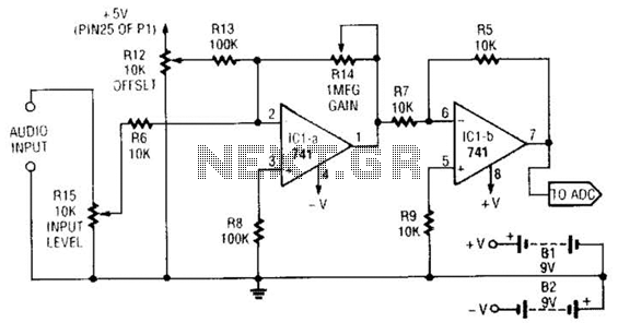
This simple general-purpose driver for an analog/digital converter uses two 741 IC devices with adjustable gain and offset. Other op-amps might be substituted, but some circuit adjustments might be needed. The circuit consists of two operational amplifiers (op-amps) from the...
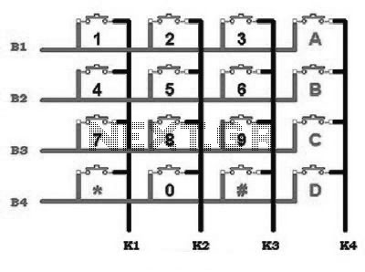
This includes an interface that is simple enough for mastery, as the keypad supports input facilities commonly used in Man-Machine Interface (MMI) applications. For example, various types of keypads can be found in the market. This discussion will focus...