
interfacing spi adc with spartan 6 fpga

The Spartan-6 board integrates a 2-channel, 12-bit SPI Analog-to-Digital Converter (ADC), specifically the MCP3202. This ADC is designed to convert analog signals into digital data, which can be processed by digital systems. The SPI (Serial Peripheral Interface) protocol facilitates communication between the Spartan-6 and the MCP3202. In this setup, the Spartan-6 functions as the MASTER, managing the clock signal (SCK) and initiating data transfers, while the MCP3202 operates as a SLAVE device.
The SPI protocol is characterized by its synchronous nature, meaning that the data transfer is synchronized with a clock signal generated by the MASTER. The communication begins with the MASTER asserting the Chip Select (CS) line low, indicating the start of a transaction. The CS line remains high when idle, ensuring that the SLAVE device is not engaged in communication unless explicitly selected.
During a SPI transaction, the MASTER sends data in 8-bit chunks, allowing for efficient data transfer. The full duplex capability of SPI ensures that while the MASTER is sending a byte to the SLAVE, it simultaneously receives a byte from the SLAVE. This bidirectional communication is essential for applications requiring real-time data exchange.
The MCP3202 provides a resolution of 12 bits, allowing for precise analog signal conversion. It supports two input channels, enabling the Spartan-6 to process multiple analog signals. The configuration allows for seamless integration into various applications, such as sensor data acquisition and signal processing systems. Proper implementation of the SPI protocol ensures reliable communication and efficient data handling between the Spartan-6 and the MCP3202, making this setup suitable for a wide range of electronic projects.The Spartan-6 board has 2-channel 12 Bit SPI ADC, indicated as in Figure. As you know in synchronous serial communication there is a clock line (SCK in case of SPI) which synchronizes the transfer. The clock is always controlled by the MASTER. In our case the Spartan6 is the MASTER and the MCP3202 is a slave on the bus. SPI is full duplex, which m eans data can be sent and received simultaneously. A SPI transfer is initiated by the MASTER pulling the CS line low. The CS line sits at HIGH during idle state. Now master can write to the bus in 8bit (or 1 byte) chunks. One most important thing to note about SPI is that for every byte MASTER writes to SLAVE the MASTER receives one byte in return. So the only transaction possible is exchange of data. 🔗 External reference
Related Circuits
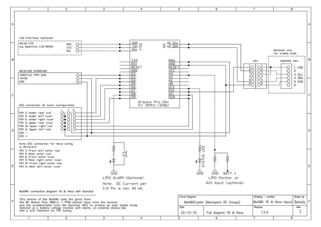
This is a video showcasing a test flight of the Quad Rotor Observer (QRO) v8, which is equipped with the FCWii board, Wii Motion Plus gyroscopes, and Nunchuk accelerometers. The Quad Rotor Observer (QRO) v8 is an advanced quadcopter designed...
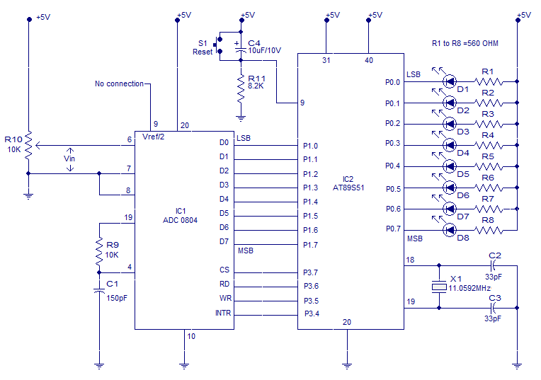
Interfacing ADC to 8051 microcontroller. ADC0804 is interfaced to microcontroller AT89S51. Complete circuit, theory and program in assembly language. The interfacing of an Analog-to-Digital Converter (ADC) with a microcontroller is a critical aspect of embedded systems design, particularly when analog...
SPICE is the most commonly used analog circuit simulator today and is enormously important for the electronics industry. SPICE is a general purpose analog simulator which contains models for most circuit elements and can handle complex nonlinear circuits. AIM-Spice...
The PSoC 3 Primer Kit is specifically designed to assist students in mastering the necessary skills in embedded systems. The kit is structured to enable easy utilization of all possible features of the microcontroller. It supports the FX2LP Programmer,...
You may find that there are too few, if your power is very noisy (as can happen in a car environment) it may help to place a 0.1uF and/or 10uF capacitor before and/or after the voltage regulator. At the...
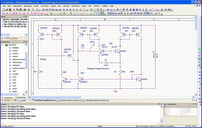
SuperSpice's philosophy is centered around the edit schematic, run simulation, view waveforms, probe signals, view waveforms, edit schematic cycle. All key issues have been automated. You can effortlessly modify the schematic, rerun and inspect new waveforms without having to...