
Interfacing to 7-Segment Displays

The integration of 7-segment displays in PLC systems offers a straightforward method for visualizing numerical data. The BCD to 7-segment decoder plays a crucial role in this process, converting binary-coded decimal inputs into the corresponding visual representation on the display. The addition of features such as the Lamp Test and Blanking inputs further enhances the usability of these displays, enabling easier maintenance and data management. The ability to multiplex displays through strobe lines allows for more efficient use of digital outputs, especially in systems where space and resources are limited. The design considerations for 24VDC operation ensure compatibility with industrial standards, providing robustness in various operational environments. Overall, the combination of these components results in a reliable and effective display solution for industrial applications, facilitating real-time monitoring and control in automation systems.In industrial PLC applications, one of the old, but simpler methods of displaying numeric information is to use one or more 7-Segment numeric displays connected to an output card of a PLC. Although it is possible to build such a display yourself, it is far more common to employ a pre-manufactured product such as the 4-digit panel mount unit shownat the top of this page.
To correctly interface a PLC to such a display, it helps to first understand what basic electronic components are typically employed in their makeup, and how this effects our task of interfacing to, and programming such a unit. Although both LED and LCD numeric displays are readily available, and interfaced similarly, we`ll concentrate on the more common LED units in the examples to follow.
Once 7-Segment LED displays became readily available, a simple IC known as a "BCD to 7-Segment decoder" was quickly developed to simplify their use. Binary formatted data presented to this IC`s inputs results in the IC`s outputs being placed into the correct state to display the equivalent numeral (0 to 9) on a 7-Segment display.
Although BCD to 7-Segment decoder ICs are available without built in latches, this particular IC includes a built in 4-bit latch which we will make use of in later examples. For now the latch is set to simply allow input data to freely pass through to the decoder. In the above diagram, the 4 toggle switches, SW0 to SW3 are used to select the desired numeral (0-9) that will appear on the 7-Segment display.
By using a decoder, it`s now simply a matter of setting the correct 4-bit BCD pattern feeding the inputs of the decoder, and the decoder takes care of the rest. The decoder section also has two additional inputs. Lamp Test (LT) turns all segments on so you can verify at once that all display segments are working, or identify display units that need to be replaced.
This input is normally left at logic 1. The Blanking (BL) input is just the reverse; it forces the entire display off. This is used in many cases to blank out leading or trailing zeros from a long display. LT will override BL so you can test even blanked-out display digits. One should also note that the same circuit could conceivably be controlled by a PLC, if 4 output bits from a 5VDC PLC output card were used in place of the 4 switches shown. If an 8-bit output card were available, then two such circuits (2 digits) could be controlled. A 16-bit card would in turn allow us to control four such circuits (4 digits). etc. The figure (above) on the left is taken from the LogixPro I/O simulator screen, and depicts a common method of interfacing to a 4 digit display.
The figures on the right are taken from the data sheet of a pre-manufactured 4 digit display unit which could be readily employed in this particular application. The manufactured unit does contain four separate circuits, and each circuit (digit) has it`s own decoder, but compared to our earlier circuit example, this unit employs additional components and circuitry making it far more versatile and easy to use.
Note that there are 4 "Strobe" lines shown; one for each digit. These strobe lines control built in IC latches which provide us with the option of multiplexing the digits, or displays, if we wished to do so. In the above non-multiplexed application, the strobes are permanently enabled allowing data to simply pass through from the BCD inputs and be displayed as normal.
Also note that this particular unit is designed for 24VDC use. This is by far the most common DC voltage level used in industrial installations, and PLC I/O cards designed for such use are therefore extremely common. In comparison to 5VDC circuits, 24VDC circuits can typically tolerate far greater supply voltage excursions, are less sensitive to the effects of contact resistance, and more tolerant of electrically noisy environments.
By making use of the 4-bit latches that are built into the 4511 IC 🔗 External reference
Related Circuits
The objective of this lab is to create a decimal counter that counts from 0 to 99 using the 80X51 microcontroller. A C program must be written for this purpose, which will then be compiled using the C51 compiler...
The TMS320C5505 Evaluation Board is specifically designed for developers in the DSP field as well as for beginners. The kit is structured in such a way that all possible features of the DSP can be easily utilized by everyone....
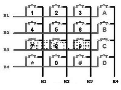
This includes an interface that is simple enough for mastery, as the keypad supports input facilities commonly used in Man-Machine Interface (MMI) applications. For example, various types of keypads can be found in the market. This discussion will focus...
After conducting experiments with a rotary encoder connected directly to keyboard switches, it was found that the keyboard controller IC (an Intel P8049AH in this case) is unable to detect pulses that are too narrow. Testing involved rotating the...
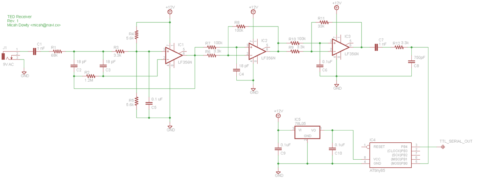
The Energy Detective (TED) is an affordable and user-friendly device designed to monitor the electricity usage of an entire household. It functions similarly to a more advanced version of a traditional utility company power meter, which can be conveniently...
Microchip has addressed the need for memory solutions with a comprehensive range of serial EEPROMs, available in various memory configurations and utilizing standard 2- or 3-wire communication protocols. The following assembly code outlines the procedure for writing and reading...