
Invisible infrared pulsed laser

The described device functions as a pulse generator that produces adjustable frequency IR pulses, which can be utilized in various applications such as remote controls, communication systems, or sensor devices. The inverter circuit plays a crucial role in converting the low voltage from the battery pack to a high voltage necessary for generating the IR pulses.
Transistor Q1 operates in a switching mode, where it alternates between conducting and non-conducting states. When Q1 is turned on, it allows current to flow through the primary winding of transformer T1, creating a magnetic field. Once Q1 saturates and turns off, the magnetic field collapses, inducing a high voltage in the secondary winding of T1. This induced voltage is then responsible for driving Q2 into saturation, facilitating the continuous generation of the pulse output.
The diodes connected to the bases of the transistors ensure that the base drive current is effectively returned, allowing the transistors to reset properly after each cycle. This feedback mechanism is vital for maintaining the stability and efficiency of the pulse generation process.
The output from the secondary of transformer T1 is a square wave voltage, which is then rectified by the integrated circuitry. Capacitor C2 serves to smooth out the rectified output, providing a stable DC voltage that can be used to power other components or systems that require a consistent voltage level for operation.
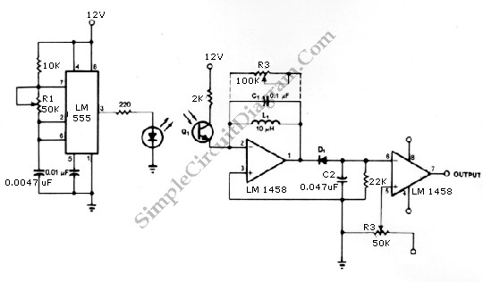
Overall, this design emphasizes the importance of careful handling due to the high voltages involved and highlights the intricate relationship between the components in achieving a reliable and adjustable IR pulse output.The device generates an adjustable frequency of low to medium powered IR pulses of invisible energy and must be treated with care. The portable battery pack is stepped up to 200 to 300 volts by the inverter circuit consisting of Ql, Q2, and Tl.
Ql conducts until saturated, at which time, the base no longer can sustain it in an "on" state and Ql turns "off," causing the magnetic field in its collector winding to collapse thus producing a voltage or proper phase in the base drive winding that turns on Q2 until saturated, repeating the above sequence of events in an "on/off" action. The diodes connected at the bases provide a return path for the base drive current. The stepped up squarewave voltage on the secondary of Tl is rectified and integrated on C2.
Related Circuits
More: A comprehensive electronic schematic for a circuit design is required. This schematic should include all relevant components, connections, and specifications to ensure proper functionality and integration into larger systems. The electronic schematic should encompass a variety of components...

IC1 generates a pulse that modulates the 1000-Hz tone generated by IC2. This circuit can be used to generate warning or alert signals. The circuit described consists of two integrated circuits (ICs), where IC1 is responsible for generating a pulse...
A compact thermal control solution for Dense Wavelength Division Multiplexing (DWDM) laser modules can be implemented using a MAX8520/21 and a single operational amplifier. The proposed thermal control solution utilizes the MAX8520 or MAX8521, which are highly efficient, low-dropout linear...
The infrared transmitter and receiver circuit depicted in the schematic diagram below can function as a remote control. The transmitter primarily operates as an oscillator. The infrared transmitter and receiver circuit is designed to facilitate wireless communication through infrared signals,...
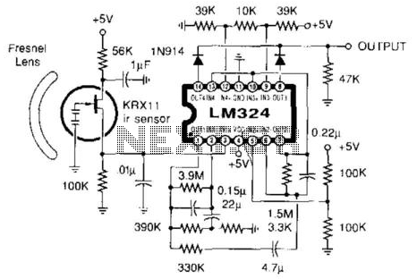
This circuit utilizes an Amperex pyroelectric infrared sensor, an LM324 operational amplifier configured as a high-gain amplifier within the 0.3 to 5 Hz frequency range, and a window detector. The output will activate (go high) upon detecting motion, which...
Free-space optical (FSO) communication utilizes light as a medium for data transmission. Communication was established between two computers using a laser, independent of any conventional communication methods. Text messages were sent from one PC to another using a system...