
IO8 Module

The circuit integrates a CAN bus communication system, utilizing the PCP2551 CAN bus transceiver (U2) to facilitate data transmission over the CAN protocol. The connection to the 2G-5 shrouded connector (N9) allows for a robust interface with external devices or systems, ensuring reliable signal integrity. The CAN bus signals are processed by the PCP2551, which converts the differential CAN signals into a format suitable for the PIC16F688 microcontroller (U1).
The PIC16F688 microcontroller serves as the central processing unit, handling both the reception and transmission of data via its UART interface. The UART signals are critical for serial communication, enabling the microcontroller to interact with other components or systems effectively. The microcontroller is interfaced with external components through a 1x3 polarized male header, which provides a convenient means for connecting additional circuitry or sensors. Each pin of this header corresponds to one of the analog inputs on the microcontroller, allowing for versatile input handling.
A half-size crystal oscillator (X1) is included in the design to provide a stable 20MHz clock signal, which is essential for the microcontroller's operation. The decision against using a resonator was made due to pin limitations; specifically, pins 2 and 3 of U1 are required for resonator connection, while pin 3 is allocated for an analog input (AN3). This careful selection of components ensures that the circuit functions optimally while adhering to the design constraints imposed by the microcontroller's pin configuration. Overall, this circuit demonstrates a well-thought-out approach to integrating CAN bus communication with a microcontroller, emphasizing reliability and functionality.The bus is connected to the 2G—5 shrouded conenctor N9. The two CAN bus signals are fed into the PCP2551 CAN bus transceiver U2. The output of U2 is fed to the UART transmit and receive signals on the PIC16F688 microcontroller U1. 8-pins of the U1 are connected to 1×3; polarized. 1" male headers. Each pin is connected to one of the anlog inpu ts on U1. A half size crystal oscillator (X1) is used to provide the reference 20MHz signal. A resonator could not be used since it requires pins 2 and 3 of U1, and pin 3 is needed for a analog input (AN3). 🔗 External reference
Related Circuits
Remote control utilizing VHF modules. Several designs for remote control switches using the VG40T and VG40R remote control pair are presented here. The miniature transmitter module illustrated in Fig. 1. The VG40T and VG40R are VHF radio frequency (RF) modules...
Circuits that utilize a temperature compensating resistor exhibit minor errors because the temperature coefficient's resistance varies as a function of temperature T, rather than the theoretically ideal inverse, 1/T. The prevalence of tempco circuits indicates that this residual error...
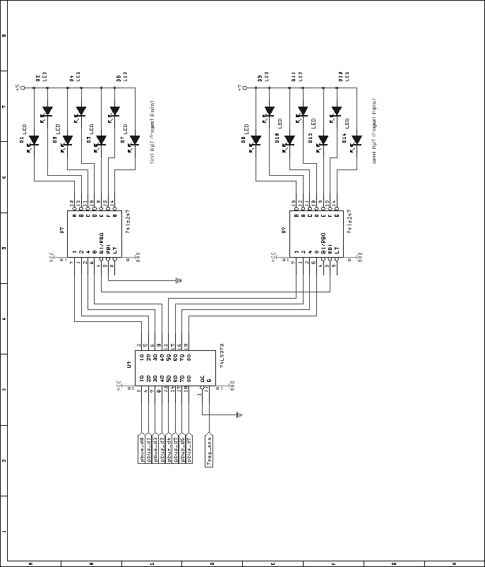
The output assignment module utilizes a 16V8 GAL for address decoding and enable signal generation. The pin assignments for the GAL used in this module are depicted in Figure 44. The VHDL code required to generate the GALs is...
This module utilizes the highly integrated MAX2830 RF transceiver, providing a complete RF front-end solution that complies with the WLAN IEEE 802.11b/g standard. The MAX2830 RF transceiver is designed for wireless communication applications, specifically targeting WLAN systems. It integrates various...
.jpg)
This project utilizes the FT232XX chip series, which functions as a USB to serial converter. These chips are capable of converting USB protocol into asynchronous serial protocol, effectively allowing the transformation of a USB1 port into a corresponding serial...

The FM497 is an integrated electronic ignition controller designed for breakerless ignition systems that utilize Hall effect sensors. This device operates an external NPN Darlington transistor to manage the coil current, thereby delivering the necessary stored energy while maintaining...