
IR Demodulator

The circuit operates by processing a 32.768 kHz IR signal through its various stages to achieve the desired output. The initial stage, which includes components up to U1A, likely serves as a signal conditioning section. U1A may function as a comparator or an amplifier, boosting the incoming IR signal to a level suitable for further processing. The output of this stage is then fed into the second stage, which encompasses the components between U1A and Q3. This intermediate stage is crucial as it likely incorporates logic gates that perform necessary signal processing, such as filtering, shaping, or generating specific logic levels based on the input conditions.
The third stage, located to the right of Q3, is expected to be the output stage, where the processed signal is converted to a logic low state when the 32.768 kHz input is present. This stage may include transistors or additional logic gates that translate the processed signal into a usable output for interfacing with other digital systems.
The presence of a resistor in series with Vcc on U1 is a common design practice to limit the current flowing into the IC, ensuring that it operates within its specified parameters and preventing damage due to excessive current. This resistor can also help in stabilizing the power supply voltage by reducing noise. R26 may serve a similar purpose, possibly functioning as a pull-up or pull-down resistor, depending on its placement in the circuit. Its specific role would require further analysis of the surrounding components and their configurations.
Overall, understanding the middle section's operation is essential for grasping the entire circuit's functionality, as it is likely where critical signal processing occurs that determines the output behavior in response to the input signal.It takes a 32. 768 kHz IR input and outputs a logic low when the input is present. I see 3 distinct stages. everything up to U1A, everything between U1A and Q3 and everything to the right of Q3. I follow the left and the right. but not the center which is where all the magic happens. Can anyone explain the piece in the middle It makes no sense to me. How is this circuit functioning Why do they make use of all the gates Why do they have a resistor in series with Vcc on U1 What purpose does R26 serve 🔗 External reference
Related Circuits
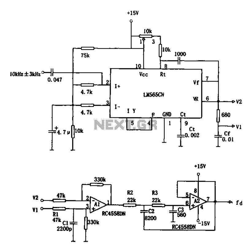
The circuit utilizes a 10 kHz and 3 kHz LM565CN to create an FM demodulation setup. The output diagram (b) illustrates the differential demodulation outputs V1 and V2 from the differential amplifier A1, which provides level displacement and amplification....
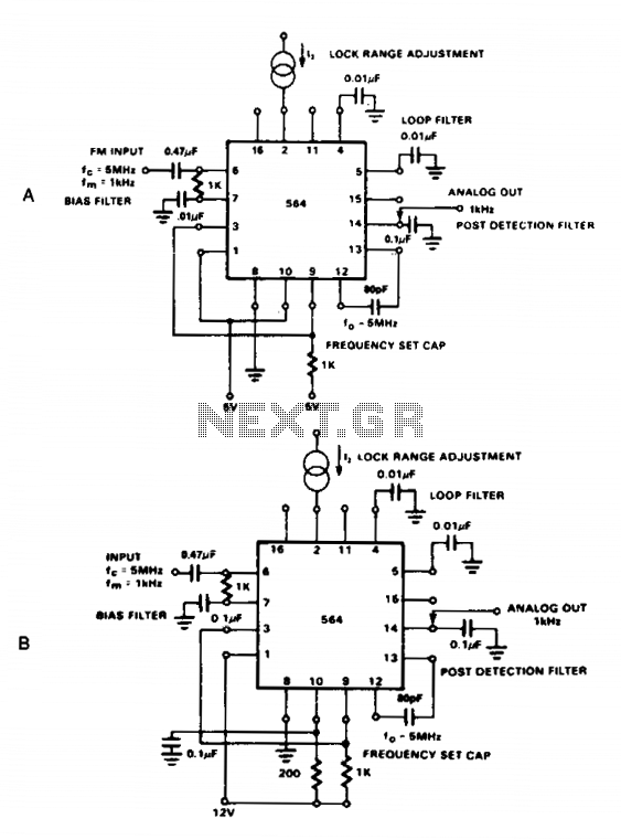
The NE564 functions as an FM demodulator. The operational connections for both 5 V and 12 V configurations are illustrated in Figures 21-4A and 21-4B. The input signal is AC coupled, with the output signal extracted from Pin 14....
The advantages of synchronous reception of AM signals are well recognized, including high selectivity, linearity of detection, and a lower noise level at the output compared to other reception methods. The circuit diagram is illustrated in Figure 1. The...
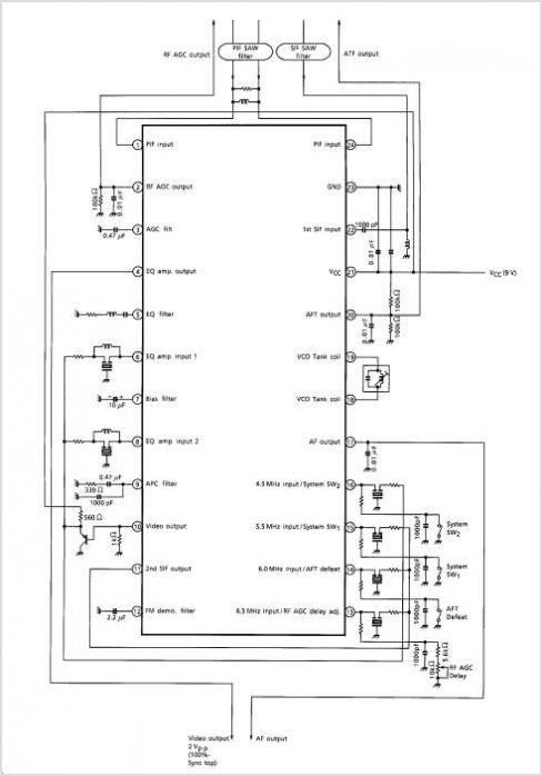
The TA1284FN is a TV tuner integrated circuit (IC) that combines a mixer and oscillator for VHF and CATV bands, a mixer and oscillator for the UHF band, and an intermediate frequency (IF) amplifier into a single chip. It...
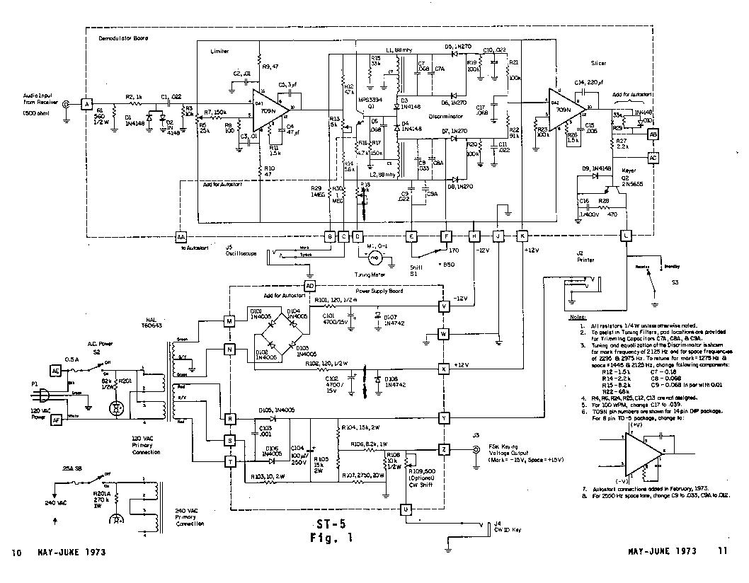
The Mainline ST-5 was introduced in the RTTY Journal in May 1970 and has quickly become a popular demodulator for RTTY. Due to the unavailability of back issues, the original article is being reprinted. Those interested in 100 baud...
Construct an accurate LC Meter (Capacitance Inductance Meter) to facilitate the creation of coils and inductors. This LC Meter is capable of measuring very small inductances, making it an ideal tool for various RF coil and inductor applications. The...