
ir sensors

The infrared emitter-detector circuit is designed for effective line detection and obstacle avoidance in robotic applications. The key components include an infrared LED, a photodetector (often a phototransistor or photodiode), and a set of resistors for current limiting and voltage division. The infrared LED emits light that is reflected off surfaces below the robot. The photodetector receives this reflected light, with its resistance changing based on the intensity of the light received.
The circuit typically includes a power supply, which can be a battery or a regulated power source, providing the necessary voltage for the components. The LED is connected in series with resistor R3 to limit the current flowing through it, preventing damage. The photodetector is connected in a voltage divider configuration with resistor R2, allowing the output voltage to vary based on the light intensity detected.
Calibration is a critical step in setting up the circuit. By measuring the output voltage when the sensor is over a white surface and then over a black surface, the operator can determine the thresholds for the comparator circuit, which can be implemented using an operational amplifier or a simple transistor switch. This comparator will output a high signal when the detected surface is white and a low signal when it is black, enabling the robot's control system to make decisions based on the detected line.
To ensure reliable operation, the design must account for environmental factors such as ambient light. Using shielding or placing the sensors in a position less exposed to direct sunlight can enhance performance. The placement of the sensors is also crucial; they should be positioned close to the ground to maximize the amount of reflected light detected from the surface below.
In summary, the infrared emitter-detector circuit is a versatile and effective solution for line detection and obstacle avoidance in robotic systems, relying on the principles of light reflection and careful calibration to function accurately in various environments.The Infrared emitter detector circuit is very useful if you plan to make a line following robot, or a robot with basic object or obstacle detection. Infrared emitter detector pair sensors are fairly easy to implement, although involved some level of testing and calibration to get right.
They can be used for obstacle detection, motion detection, tr ansmitters, encoders, and color detection (such as for line following). In order to detect a line, we use the principle of reflection of light over different colors. As we all know, a white color object reflects almost all light incident on it while a black colored object absorbs all. Now, by measuring the variation in the intensity of reflected light we can easily determine the presence/absence of line under the sensor.
We use an IR LED which will emit Infrared light and it will be reflected by the surface. The detector acts as a variable resistor whose value depends on the intensity of light falling on its surface. The higher the intensity, the lower is the resistance of the detector. The detector and R2 act as a potential divider. When the intensity is high (reflected from white surface), the resistance of detector is low and so the value of the potential is high.
Similarly when the intensity is low (reflected from black surface), the resistance of the detector is high and so the potential is low. This potential is compared with a reference potential. The reference can be varied by the potentiometer (pot). Calibration is required. You have to record potentials of the white as well as black surface and then find their ranges. According these potentials ten set the reference so that for white surface output is. high and for white black surface output is low. R3 resistor prevents excessive current to pass through the LED. The value of the resistor depends on the size and the colour of the LED. More the diameter of the LED, more is the current it will sink in. R1 should be chosen according to the LED. Usually for 3mm Red LED and 5V supply 330 is enough. R2 should be larger then the maximum resistance of the detector. If you work in the sunlight make sure it doesn`t interfere with the function of the circuit. Usually sensors placed below the body of the robot are the least affected by it. 🔗 External reference
Related Circuits
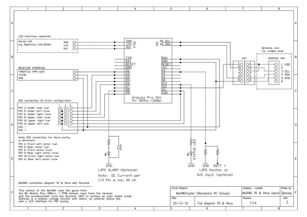
This is a video showcasing a test flight of the Quad Rotor Observer (QRO) v8, which is equipped with the FCWii board, Wii Motion Plus gyroscopes, and Nunchuk accelerometers. The Quad Rotor Observer (QRO) v8 is an advanced quadcopter designed...
.jpg)
The inductive sensor is a straightforward device at its core. It consists of a coil of wire with an electric current flowing through it. This sensor primarily ignores most objects that come close to the coil. However, when a...
Although the Arduino effectively captures incoming sensor data, executing code typically in the microsecond range, challenges arose in transmitting data between the Arduino and Max. The data transfer speed was insufficient. The focus was primarily on creative project realization...
A few years ago, a diode-sensor based RF power meter was built using a 68HC11 microprocessor. Prior to that, an analog RF power meter with a thermal power sensor was developed. The datasheets for logarithmic amplifiers, which promised a...
The SP1481E, SP1485E, SP1490E, and SP1491E series transceivers, combined with the SP6652 high-efficiency, high-frequency current mode PWM buck regulator, facilitate the creation of an isolated RS-485 interface capable of providing up to 2kVrms isolation. This configuration supports CAN communication...
The TPA2011D1 is a 3.2-W high-efficiency, filter-free Class-D audio power amplifier housed in a 1.21 mm x 1.16 mm wafer chip scale package (WCSP) that requires only three external components. This amplifier features 95% efficiency, an 86-dB power supply...