
It used to delay the monostable multivibrator circuit diagram of a continuous sequence

The Exar XR-2556 is a versatile dual timer IC designed for precise timing applications. It operates with a supply voltage of 4.5V to 16V, making it suitable for a variety of electronic circuits. The timing intervals are determined by external resistor-capacitor (RC) networks connected to each timer channel. The output of the first timer (Output 1) can be programmed to remain high for a duration T1, which is calculated using the formula T1 = 1.1 * R1 * C1, where R1 is the resistance in ohms and C1 is the capacitance in farads.
Upon triggering the first timer, the output will initially increase, providing a high signal for the duration specified by T1. Following this, the output will decrease, transitioning to a low state, which is controlled by the second timer (Output 2). This second timer can be triggered through a capacitive coupling mechanism, allowing for flexible timing applications. The duration T2 for the second timer is similarly defined by the equation T2 = 1.1 * R2 * C2.
Pin 13 of the XR-2556 plays a crucial role in extending the timing capabilities of the device, effectively allowing for the creation of monostable multivibrator functions. This feature is particularly useful in applications requiring precise timing control, such as pulse generation, delay circuits, or signal conditioning. The maximum output current is limited to 200mA, ensuring that the device can drive moderate loads without risk of damage.
Overall, the Exar XR-2556 dual timer is an effective solution for implementing timing functions in electronic circuits, providing designers with the flexibility to create complex timing sequences and control logic in a compact and efficient manner.Dual Timer Exar XR-2556 for the first time after the timing of the output can be triggered by capacitive coupling second timing pin. When the trigger input is used, in order to be able to equal the duration T1 1.1R1C1, output 1 will be increased, then decreased by CC-shot timer 2. Pin 13 is then also increased its duration T2 equal 1.1R2C2, its function and delay monostable multivibrator function is the same.
Supply voltage 4.5-16V. R can keep the timing of the supply voltage output below 200mA.
Related Circuits
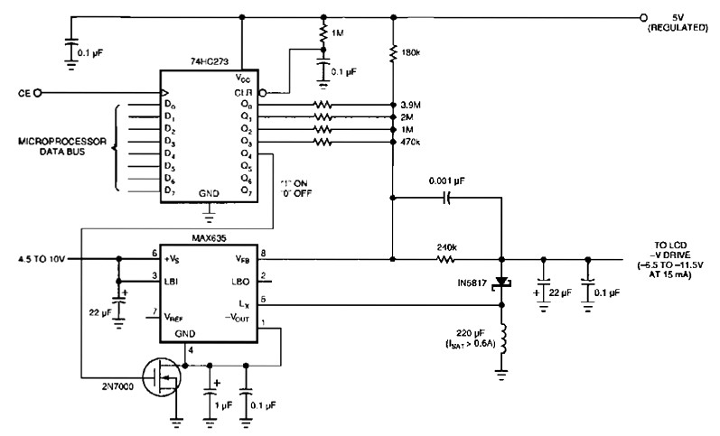
The following figure's switching regulator generates a negative voltage from the notebook battery supply. The microprocessor data bus drives a 4-bit DAC (74HC273), which can vary the regulator output between 6.5 to 11.5 V. This arrangement enables a staircase...
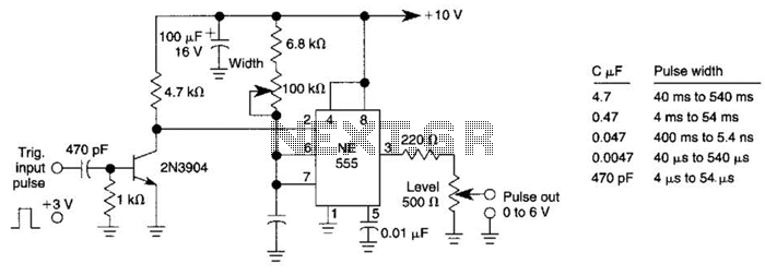
This pulse generator can enhance a standalone pulse generator. By utilizing a transistor and a 555 timer, it can produce pulse widths ranging from 5 microseconds to 500 microseconds. The value of capacitor C3 can be approximately determined using...
The diagram illustrates a human infrared remote sensing lamp circuit. It utilizes the trace infrared heat emitted by humans to control the lamp's operation, allowing it to turn on or off remotely. This human infrared remote sensing lamp features...
The digital visitor counter is a reliable circuit designed to accurately count the number of persons or visitors in a room. When an individual enters the room, the counter increments by one, and when someone leaves, the counter decrements...
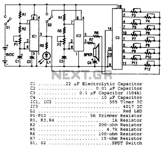
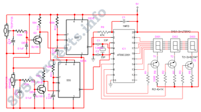
Three integrated circuits (ICs) are utilized to generate sounds. IC1 is a 555 timer configured as an astable multivibrator, producing clock pulses. The frequency of these clock pulses is adjustable via a trimmer potentiometer, P1. These clock pulses are...
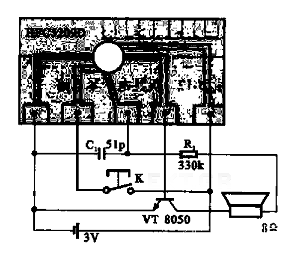
A simple phone automatically displays the recording circuit. In this circuit, after the call, the Ming sound start switch K is activated by the sound of the automatic message HFC5209D. The described circuit functions as an automatic call recording system...