
Knightrider lights for model cars

The circuit for the Knightrider scanner mode employs a 555 timer IC, specifically the CMOS variant (7555), which is known for its low power consumption and versatility in timing applications. The configuration typically used is astable, generating a square wave output that alternates the LEDs in a sequential manner, creating a visual effect reminiscent of the iconic "KITT" scanner from the television series.
The circuit consists of six LEDs arranged in a linear fashion. Each LED is connected in series with a current-limiting resistor to prevent excessive current flow, which could damage the LEDs. The output from the 7555 timer drives a series of flip-flops or a decade counter, which sequentially activates each LED in a specific order, producing the desired scanning effect.
The power supply for the circuit can vary depending on the LED specifications and the design requirements; however, a common voltage range is between 5V and 15V. It is crucial to select appropriate resistors to ensure that the current through each LED does not exceed its rated specifications, typically around 20 mA for standard LEDs.
For enhanced functionality, additional components such as capacitors may be included to stabilize the voltage and improve the timing accuracy of the 555 timer. The choice of LEDs can also affect the overall power consumption and brightness of the display, making it essential to consider the forward voltage and current ratings of the selected LEDs when designing the circuit.
Safety precautions should be observed when assembling and testing the circuit. Proper insulation, the use of breadboards or prototyping boards, and adherence to standard electrical safety practices are recommended to minimize the risk of electric shock or damage to components.This simple circuit drives 6 LEDs in `Knightrider scanner mode`. Power consumption depends mainly on the type of LEDs used if you use a 7555 (555 CMOS version). We are not responsible for any injuries or damage caused by information from this website! Working with electricity is dangerous for your life, especially diagrams related to high voltage! We do not guarantee success in building devices using our diagrams! They are not tested by us. For questions about diagrams use author info below diagram or our contact page. Thank you! 🔗 External reference
Related Circuits
This is a handmade prototype research project designed to demonstrate the components of a tracker and to assist in the development of tracker-related magnetic-field models. It is not intended as a commercial product. Functions that are necessary for a...
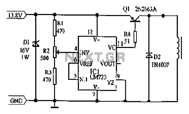
Cars are equipped with a circuit that includes an LM723 regulator, which can serve as a replacement for traditional automobile generator systems that utilize electromechanical charging regulators. This circuit offers superior performance compared to conventional systems. It ensures that...
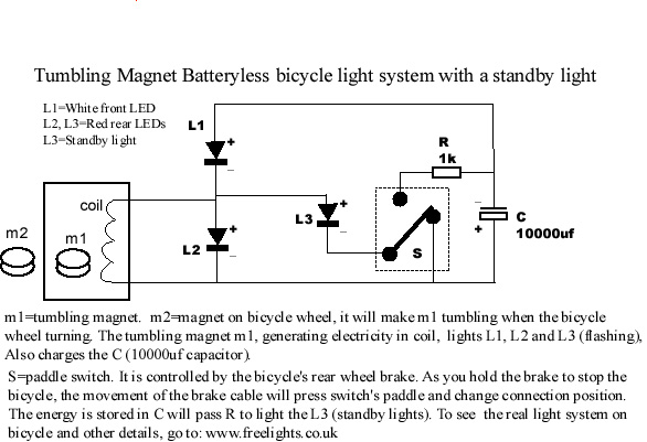
This bicycle safety flashing light system is based on a newly invented electrical generation system that requires no battery and produces no friction on any parts of the bicycle. It generates energy with minimal resistance, making it highly efficient...
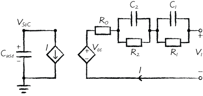
Wolfram SystemModeler includes model libraries for various domains such as electronics, mechanics, and biochemistry. A new addition to this collection is the SystemDynamics library, created by François E. Cellier and Stefan Fabricius. System dynamics, a methodology established by Jay...
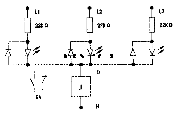
The circuit illustrated below activates a small relay (J) when there is an imbalance in any one phase of a three-phase circuit. This relay triggers an external control contact, which immediately disconnects the power supply to the main circuit...
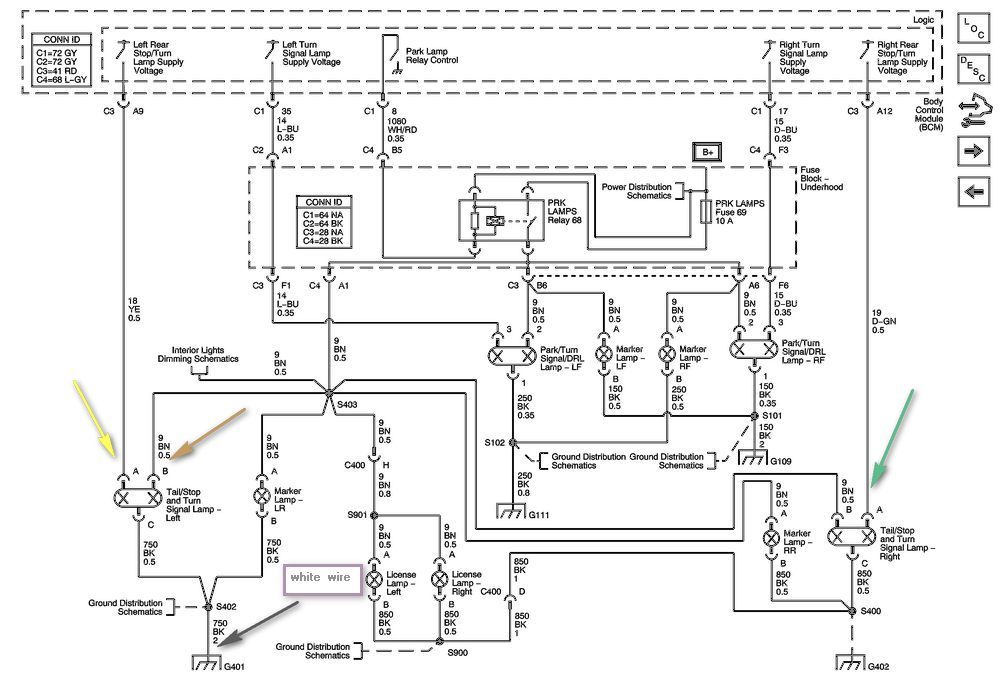
The left side of the vehicle operates correctly, with the running lights and brake light functioning properly. However, the turn signal is not working when wired directly into the harness. There is a preference to avoid purchasing a plug-in...