
L297/298 Stepper Motor Controller

The stepper motor controller circuit is designed to facilitate precise control of stepper motors, which are commonly used in applications requiring accurate positioning. The PCB layout integrates various components, including a microcontroller, driver ICs, and power supply elements, ensuring efficient operation and compact design.
The microcontroller serves as the central processing unit, executing control algorithms that determine the stepping sequence of the motor. It interfaces with the stepper motor driver ICs, which amplify the control signals and provide the necessary current to the motor coils. The inclusion of the Schmitt trigger is critical, as it enhances signal integrity by providing hysteresis, which helps to eliminate false triggering caused by noise or voltage fluctuations. This feature is particularly beneficial in environments with electromagnetic interference.
The power supply section of the PCB is designed to deliver stable voltage levels required for the operation of both the microcontroller and the stepper motor. It may include voltage regulators to ensure that the components receive appropriate power levels, thus enhancing the overall reliability of the system.
In summary, the stepper motor controller PCB not only simplifies the assembly process but also incorporates thoughtful design improvements that enhance performance and reliability. The integration of experienced insights into the design process further contributes to the robustness of the final product.A better way to make a stepper motor controller is to make a printed circuit board, and then simply drop the components in. After making the PCB, placing the components and soldering them hardly takes any time at all, in contrast to the proto board which took a ton of time to make.
Here`s a picture of the first stepper motor controller I made in PCB-form: Here is the schematic for the PCB version of my stepper motor controller. Notice that some improvements were made, such as the Schmitt trigger to help filter out noise. I want to thank Phil for his help when I was designing the PCB. He has a lot of experience with these stepper motor ICs and gave me a lot of advice. I also borrowed the idea of using a Schmitt trigger from him. 🔗 External reference
Related Circuits
The artwork style of the operational amplifier and the meter face suggests that it is an ACC design from an old issue of ACC Notes. The second image was scanned, and the text below was written from scratch. If...
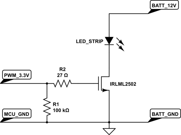
A strip of LEDs is controlled by a microcontroller using pulse-width modulation (PWM) to adjust brightness. The LED strip requires approximately 1.5A at 12V. The user, who has experience only with low-power digital electronics, seeks confirmation of their assumptions...
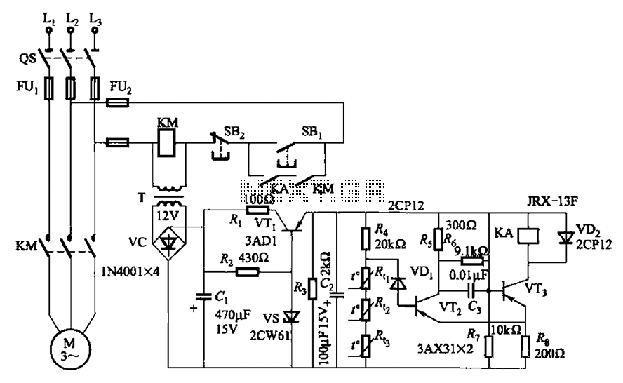
A P-type transistor (VT2, VT3) and other components form a common emitter-coupled trigger, functioning as a Schmitt trigger device. This setup serves as a switching circuit to detect changes in the resistance of a PTC thermistor, thereby controlling the...
Many applications require a large number of keys connected to a computing system. Examples include PC keyboards, cell phone keypads, and calculators. Connecting a single key to a microcontroller unit (MCU) is straightforward; however, connecting 10 or 100 keys...
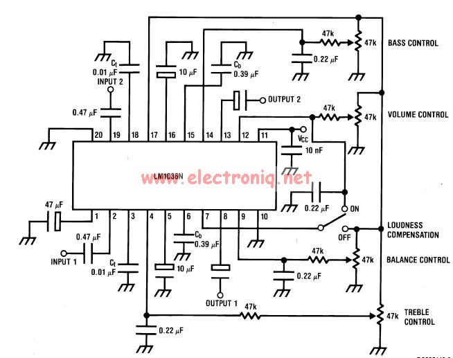
This volume controller equalizer electronic project is designed using the LM1036 DC tone volume controller, featuring a volume and balance circuit for stereo applications. The four control inputs of the LM1036 volume controller enable the control of bass, treble,...
Average vending machines are commonly found at railway stations, airports, fast-food restaurants, and even within companies. When a switch is pressed, the machine dispenses a cup of the selected beverage. Although this process appears straightforward, it involves complex logic,...