
Lamp-flasher

The circuit consists of two power FETs configured as a simple astable multivibrator to alternately switch two lamps on and off. The resistor-capacitor (RC) values set the flash rate to approximately 1/3 Hz. By varying either the resistor or capacitor values, nearly any flash rate can be achieved. Increasing either C1 and C2 or R1 and R2 will slow the flash rate, while decreasing them will increase the rate.
The described circuit utilizes two power Field Effect Transistors (FETs) to create an astable multivibrator configuration, which is essential for generating a square wave output. This output is used to drive two lamps, allowing them to turn on and off alternately. The frequency of the flashing effect is determined by the timing components, specifically the resistors (R1, R2) and capacitors (C1, C2) connected in the circuit.
In an astable multivibrator, the two FETs are arranged in a feedback loop that continuously switches states. When one FET turns on, it allows current to flow through one lamp, while the other FET turns off, preventing current through the second lamp. This alternating action creates a visual effect of flashing lights. The rate of this flashing can be finely tuned by adjusting the RC values.
The relationship between the RC values and the flash rate is inversely proportional; as the capacitance or resistance increases, the time constant of the circuit rises, resulting in a slower flash rate. Conversely, reducing the values of C1, C2, R1, or R2 will decrease the time constant, leading to a quicker flashing effect.
In practical applications, selecting the right values for the resistors and capacitors allows for a wide range of flashing frequencies, making this circuit versatile for various lighting applications. The design can be implemented on a PCB or a breadboard for prototyping, ensuring that proper heat dissipation for the power FETs is considered to maintain reliability during operation.The circuit is built around two power FETs, which are configured as a simple astable multivibrator to alternately switch the two lamps on and off. The rc values given sets the flash rate to about 1/3 Hz. By varying either the resistor or capacitor values, almost any flash rate can be obtained. Increase either Cl and C2, or Rl and R2, and the flash rate slows. Decrease them and the rate increases.
Related Circuits
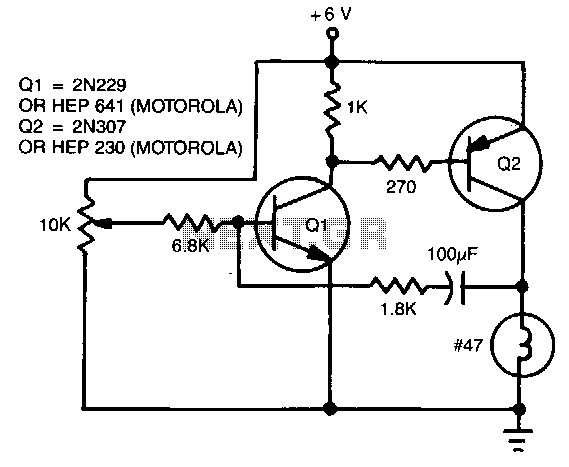
The flash rate is controlled by a complementary multivibrator consisting of an NPN and a PNP transistor. The complementary multivibrator circuit is a fundamental electronic configuration used to generate square wave signals, which can be employed for various applications including...