
Lamp Flasher

The circuit operates by utilizing a series of flash bulbs that are energized in a controlled manner. The key components include two transistors, Q1 and Q2, which are configured to provide the necessary biasing for the circuit operation. When activated, the transistors allow current to flow through the bulbs, causing them to emit light. The LM195 serves as a current limiter, ensuring that the bulbs do not experience excessive current during the turn-on phase. This is particularly important for cold bulbs, which can draw significantly higher currents when first energized.
The timing of the flashing is controlled by the circuit's design, which is intended to produce a flash approximately every second. This timing can be adjusted by modifying the values of the timing components, such as capacitors and resistors, if they are included in the circuit. The use of the LM195 not only protects the bulbs but also helps in managing power consumption, making the circuit efficient and reliable.
In summary, this electric lamp flasher circuit is designed to provide a reliable and efficient method for flashing 12V bulbs while ensuring longevity and reduced electrical strain. The careful selection of components and their configuration allows for optimal performance, making it suitable for various applications where flashing lights are required.This circuit is a series of electric lamps Flasher. This circuit is designed for flash bulb 12V approximately one-second per level. Base behind when Q2 Q1 provides biasing to eliminate the need for a resistor. Typically, a cold light bulb can be pulled eight times the normal operating current. Since the LM195 is current limited, high peak current to the bulb is not experienced during the turn-on. This extends the life of the ball as well as reduce the burden on electricity. Here is a schematic drawing: 🔗 External reference
Related Circuits
This circuit gradually illuminates a 120VAC lamp over an approximate 20-minute period. A bridge rectifier provides 120V DC to the MOSFET and the 60-watt lamp. A 6.2K, 5-watt resistor and a zener diode are employed to reduce the voltage...
The timing components are R1, R2, and C1. C1 is a bypass capacitor used to reduce the effects of noise. At start-up, the voltage across C1 is less than the trigger level voltage (1/3 Vcc), causing the timer to...
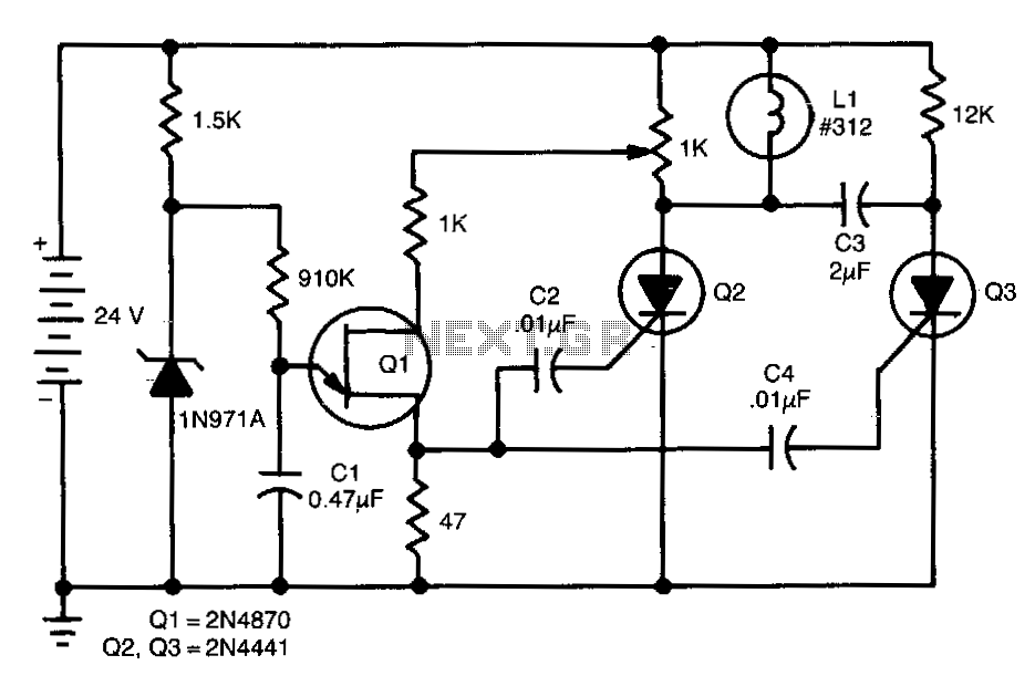
This de-flasher utilizes two SCRs and a unijunction oscillator clock to establish the flash rate, which can be adjusted by modifying the value of C1. The circuit described operates as a de-flasher, a device commonly used in lighting applications...

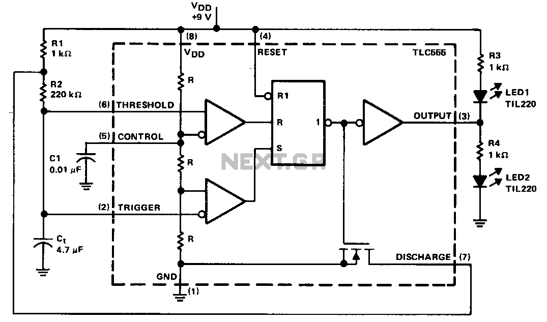
This circuit utilizes a low-cost CMOS integrated circuit (IC) to control four light-emitting diodes (LEDs), turning them on and off at a frequency determined by the resistor values R1 and R2, as well as the capacitor values C1 and...
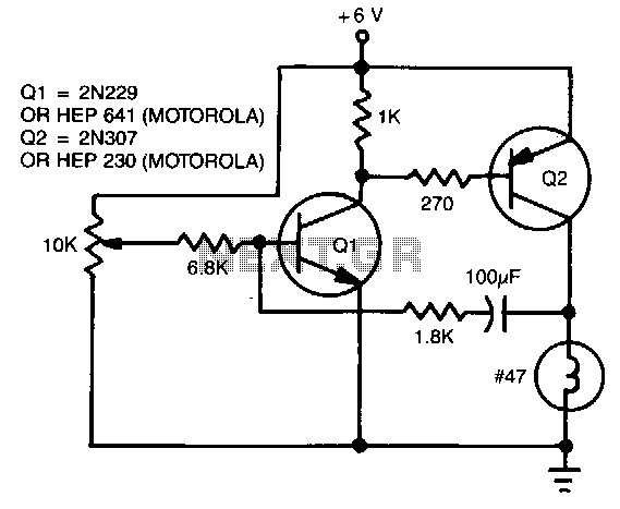
The flash rate is controlled by a complementary multivibrator consisting of an NPN and a PNP transistor. The complementary multivibrator circuit is a fundamental electronic configuration used to generate square wave signals, which can be employed for various applications including...
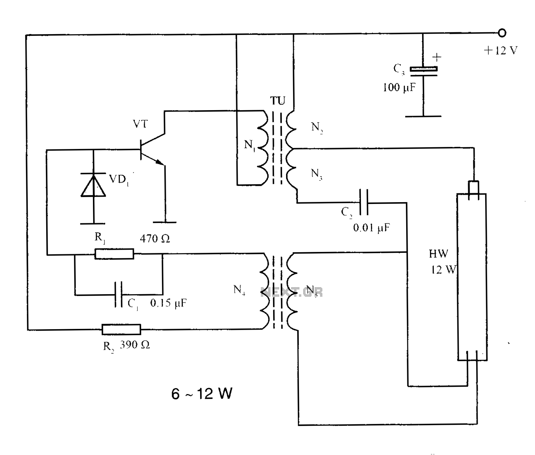
The lighting inverter circuit is designed for 6 to 12W fluorescent lamps. It operates by first bucking the mains voltage, followed by rectification and filtering to charge a battery. When the inverter is activated, it generates a high-frequency alternating...