
Laser-diode-pulsers

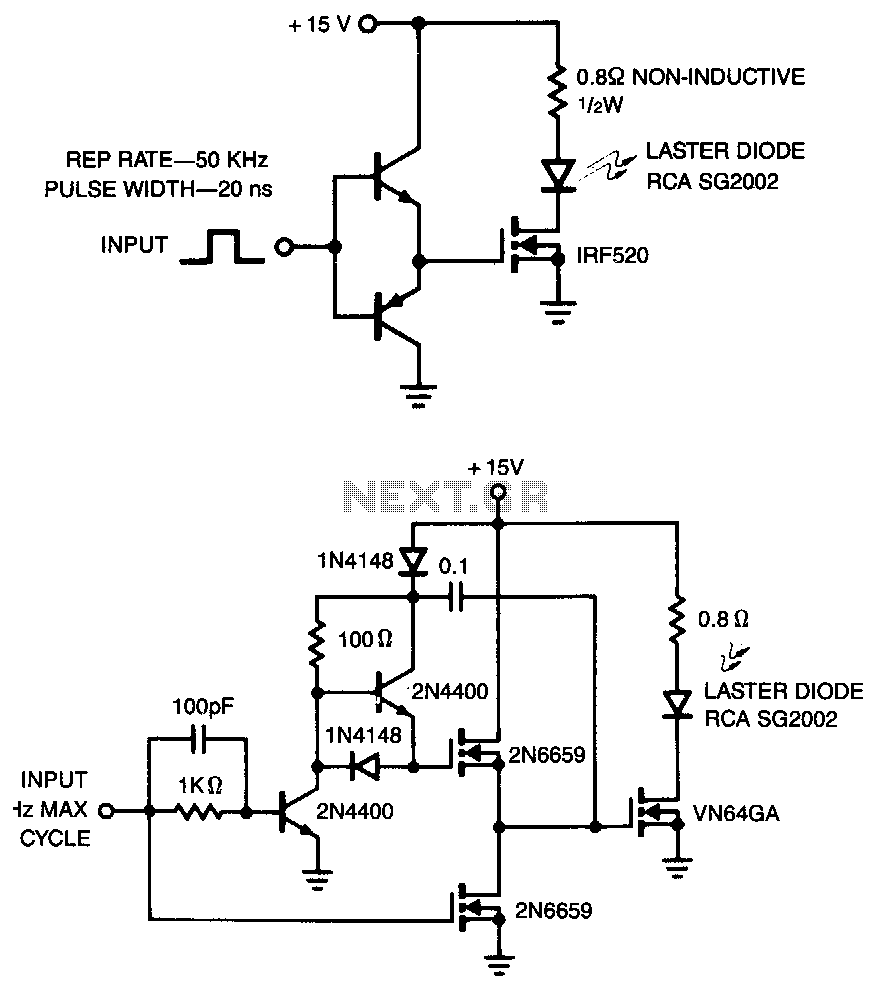
The laser diode pulser is a simple drive circuit capable of driving the laser diode with 10 A, 20 ns pulses. For a 0.1% duty cycle, the repetition rate will be 50 kHz. A complementary emitter follower is used as a driver. The switching speed is determined by the hFE of the bipolar transistors used and the impedance of the drive source. A faster circuit is shown, which can supply higher peak gate current to switch the IRF520 very quickly. This circuit uses a MOSPOWER totem-pole stage to drive the high-power switch. The upper MOSFET is driven by a bootstrap circuit. Typical switching times for this circuit are about 10 ns for both turn-on and turn-off.
The laser diode pulser circuit operates by delivering precise, high-current pulses to a laser diode, enabling effective modulation and control of the laser output. The design incorporates a complementary emitter follower configuration, which serves as the driver stage, allowing for efficient current amplification while maintaining a low output impedance. This configuration is critical for achieving the desired pulse characteristics, particularly for applications requiring rapid switching.
The switching speed of the circuit is influenced by the current gain (hFE) of the bipolar transistors employed in the design and the impedance characteristics of the drive source. A careful selection of these components is essential to optimize performance and ensure that the circuit can handle the required switching frequencies without distortion or degradation of the pulse shape.
Additionally, the circuit includes a MOSPOWER totem-pole stage, which enhances the drive capability for the high-power switch, specifically the IRF520 MOSFET. This arrangement allows for the rapid charging and discharging of the gate capacitance of the MOSFET, resulting in significantly reduced switching times. The use of a bootstrap circuit to drive the upper MOSFET further improves the efficiency of the switching process, enabling typical turn-on and turn-off times of approximately 10 ns.
In summary, the laser diode pulser circuit is a sophisticated design that effectively combines various electronic components to achieve high-speed operation and precise control of laser diodes, making it suitable for a range of applications in photonics and optical communications.The laser diode ·pulser is a simple drive circuit capable of driving the laser diode with 10-A, 20-ns pulses. For a 0. 1 % duty cycle, the repetition rate will be 50 kHz. A complementary emitter follower is used as a driver. Switching speed is determined by the h of the bipolar transistors used and the impedance of the drive source.
A faster drive circuit is shown. It can suwly higher peak gate current to switch the IRF520 very quickly. This circuit uses a MOSPOWER totem-pole stage to drive the high power switch. The upper MOSFET is driven by a bootstrap circuit. Typical switching times for this circuit are about 10 ns for both tum-on and tum-off. We aim to transmit more information by carrying articles. Please send us an E-mail to wanghuali@hqew. net within 15 days if we are involved in the problems of article content, copyright or other problems. We will delete it soon. 🔗 External reference
Related Circuits
The laser diode pulser is a straightforward drive circuit designed to operate a laser diode with 10 A, 20 ns pulses. With a duty cycle of 0.1%, the repetition rate reaches 50 kHz. A complementary emitter follower serves as...