
Laser Power Supply

The circuit described utilizes a 555 timer (IC1) configured in astable mode to generate a square wave signal at a frequency of approximately 16 kHz. This frequency is suitable for driving a power transistor (Q1), specifically a TIP146, which acts as a switch to control the primary side of transformer T1. The transformer steps up the voltage, allowing for high voltage generation across its secondary winding. The output voltage can vary significantly, ranging from 800 to 2,000 V, which is then further doubled to achieve a high-voltage output of 3 to 5 kV, essential for applications such as laser excitation.
The circuit includes a feedback mechanism that monitors the load on the power supply. As the load increases, transistor Q2 is triggered, which activates relay RY1. The engagement of the relay modifies the duty cycle of the 555 timer, allowing for dynamic adjustment of the output voltage to meet the demands of the load.
For calibration, resistors R12 and R13 are critical components. They are initially set to their mid-range values, allowing for fine-tuning of the circuit's response. Adjusting R12 influences the triggering of the laser tube; if the laser does not ignite, further adjustments to R12 are necessary. Should the relay exhibit chattering behavior during operation, indicating instability, additional tuning of R12 is required until stable operation is achieved. In cases where the laser tube does not ignite despite maxing out R12, it is advised to adjust R13 to ensure proper functioning of the circuit.
This design exemplifies a robust method for generating high voltage for laser applications, with built-in adjustments for load variations, ensuring reliable performance and operational flexibility. ICl is a 555 timer running at about 16 kHz. This IC drives Ql, a TIP146, which produces a 12-V square wave across Tl pri mary. This produces between 800 and 2,000 V across the secondary, which is doubled to 3 to 5 kV. When the load (laser) on the power supply increases, current Q2 is turned on, which energizes RY1. This changes the duty cycle of the 555 timer, lb adjust this supply, set R12 and R13 at the center. Adjust R12 until the laser tube triggers, and make sure that the relay pulls in. If the relay chatters, adjust R12. If the full-clockwise adjustment of R12 fails to ignite the tube, adjust R13.
Related Circuits
Most amplifiers operate at acoustic frequencies, sometimes requiring two or even three transformers instead of a single power transformer. This approach is more prevalent in high-end amplifiers, where enthusiasts often prioritize high fidelity over cost. In these setups, the...
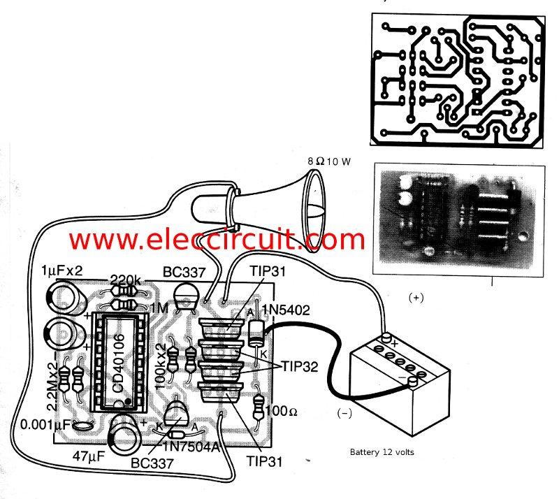
This is a simple siren sound generator with high power output and significant noise. The circuit utilizes digital ICs, specifically the CD4046, in an inverter configuration, along with four transistors to amplify the current output to a horn speaker...
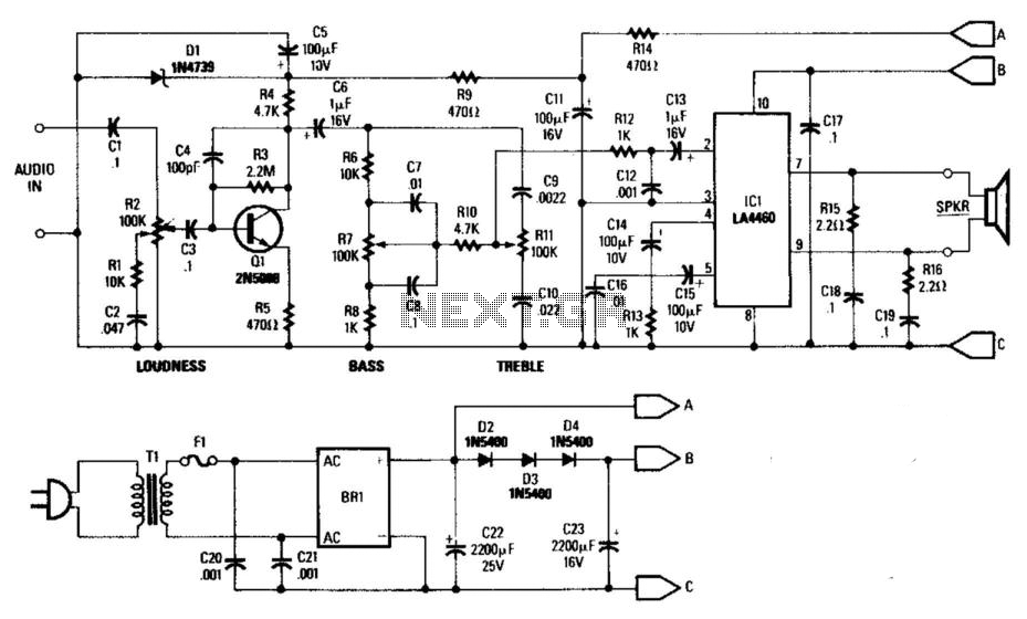
This general-purpose low-power (5 W) audio amplifier is designed to drive speakers ranging from 8 to 12 inches. It utilizes a Sanyo LA4460 integrated circuit (IC) as the audio output component. The circuit features a loudness control, a driver...
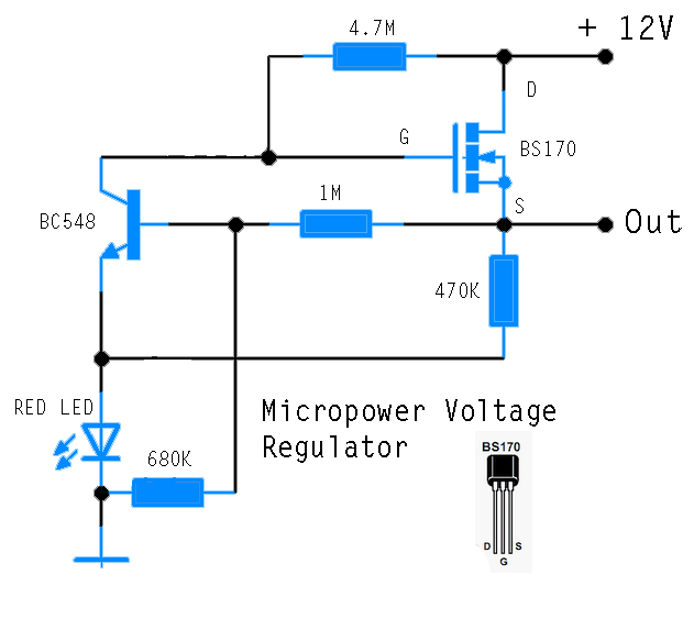
This circuit is designed to power an AVR microcontroller from a 12V lead-acid battery. The watchdog component consumes only 14 µA. While integrated circuits (ICs) from manufacturers like Linear Technology or Maxim can be utilized for this purpose, they...
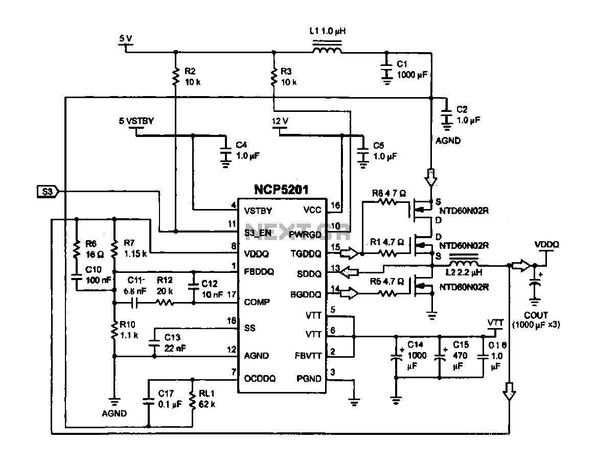
Computer memory power supply circuit (NCP5201). This circuit illustrates a typical power supply configuration for computer memory, utilizing the NCP5201 power management chip. It features a dual-output design. The NCP5201 is a highly integrated power management solution designed specifically for...
All miniature electronic devices operate off batteries. Some of them require higher than the standard battery voltages for efficient operation. If a battery with the specific voltage is unavailable, additional cells must be connected in series to increase the...