
LC179 utilizing temperature and humidity limit alarm circuit diagram

The LC179 is constructed using a temperature and humidity limit alarm circuit. The main circuit configuration and component selection include a power circuit, an astable multivibrator, a temperature control circuit, and a thyristor control circuit. The power supply circuit consists of a power switch (S), AC insurance (FU), a power transformer (T), a rectifier bridge (UR), filter capacitors (C1, C7), and a current limiting resistor (R6). In practical applications, a 5A, 250V power switch is often used for S; T is selected with a power rating of 5 to 10W and a secondary voltage of 15V; UR is typically a 1A, 50V rectifier bridge. The circuit steps down the 220V AC voltage, rectifies, and filters it to provide nearly 18V DC for the optocoupler's internal LED. Another path with limiting resistor R6 and capacitor C7 is filtered to supply operating power to IC1 and IC2.
The astable multivibrator is based on the NE555 integrated circuit (IC1), which employs resistors (R2, R3) and capacitors (C2, C3) as peripheral components. For precise temperature control, the monostable CD4538 (IC2) is paired with a thermistor (RT), a potentiometer (RP), resistors (R4, R5, R7-R9), and capacitors (C4-C6), along with electronic switches (VD1, VD2). In practical applications, RT is typically a negative temperature coefficient thermistor, while RP is a small synthetic carbon potentiometer. The diodes VD1 and VD2 are often IN4148 silicon switching diodes or ZAK10 type germanium switching diodes.
The thyristor control circuit consists of a transistor (VT), an optocoupler (VLC), and a TRIAC (VS), which are used to control heating appliances. In practical applications, VT is often an S9013 or S8050 silicon NPN transistor, VLC is commonly a 4N25 optocoupler, and VS is selected to be a TRIAC rated for 1A and 100V or higher. The heating element (EH) is typically a PTC heater.
Working principle: Once powered, the astable multivibrator operates, generating a square wave output pulse signal from pin 3 of the NE555. This pulse signal is processed through C4 and R4 and then triggers the two monostable circuits inside the CD4538 via pins 4 and 12. The pulse width is compared, and when the output at pins 6 and 9 of the CD4538 is high, electronic switches VD5 and VD6 turn off simultaneously. This allows VT to enter a conduction state, lighting the internal LED of the optocoupler VLC, which in turn activates the phototransistor. This triggers the TRIAC (VS) to conduct, energizing the heating element (EH) to begin heating.
As the liquid temperature increases, the resistance of the thermistor (RT) decreases. When the temperature reaches the set point determined by the potentiometer (RP), the output at pin 6 of the CD4538 transitions from high to low, causing VD5 to conduct. This action turns off VT, VS, and VLC, stopping the heating process. When the liquid temperature drops below a certain threshold, the output at pin 6 returns high, turning VD5 off and allowing VT, VS, and VLC to conduct, thus restarting the heating cycle. This process continues, maintaining the liquid temperature close to the set value determined by RP. CD4538 is using DIP-16 and SMD-16 packages precision monoflop. With stable performance, fewer required external components, the logic function is strong, the chip integrates tw o independent single-shot, which is widely used in counting, divide and temperature control and other fields. Typical infusion fluid heating circuit utilizes CD4538 controller configuration shown in FIG. The controller When the liquid temperature and the body temperature is too large temperature difference can be pulse-width temperature control for heating infusion, in order to reduce the pain when the patient infusion, chills and other symptoms, is safe, efficient and so on.
LC179 constructed utilizing temperature and humidity limit alarm circuit The main circuit configuration and component selection: The figure shows that the infusion fluid heating controller from the power circuit, astable multivibrator, temperature control circuit and thyristor control circuit. Among them, the power supply circuit from the power switch S, AC Insurance FU, power transformer T, rectifier bridge pile UR, filter capacitor C1, C7 and current limiting resistor R6 and other components.
Practical application, S often used 5A, 250V power switch; T selected 5 ~ 10W, 15V secondary voltage of the power transformer; UR selected 1A, 50V rectifier bridge heap. 220V AC voltage step-down after the adoption, rectified and filtered all the way to provide nearly 18V DC voltage optocouplers VLC internal LED; another path limiting R6 and C7 filtered for IC1 and IC2 operating power.
Astable multivibrator from when base integrated circuit IC1 and resistors R2, R3, capacitors C2, C3 and other peripheral components. Practical application, IC1 NE555 type used when the base often integrated circuits. Precise temperature control circuit by a monostable CD4538 (IC2) and thermistor RT, potentiometer RP, resistors R4, R5, R7 ~ R9, capacitor C4 ~ C6, electronic switch VD1, VD2 and other peripheral components.
Practical application, RT often used negative temperature coefficient thermistor; RP use of small synthetic carbon potentiometer; VDI and VD2 use IN4148 silicon switching diode or ZAK10 type germanium switching diodes. Thyristor controlled circuit by the transistor VT, optocouplers VLC, TRIAC VS EH composition and heating appliances.
Practical application, VT often used S9013 or S8050 silicon NPN transistor; VLC selection 4N25 optocoupler; VS selection 1A, 100V above Triac; EH chosen PTC heater. working principle: After the circuit is powered, astable multivibrator electrical work, NE555 3 feet square wave output pulse signal, the pulse signal after C4 and R4 differential treatment, 4 and 12 feet from the CD4538 input trigger inside the chip two monostable circuit, and pulse width comparison.
When CD4538 6 feet and 9 feet high while the output, electronic switches VD5, VD6 off simultaneously, so that VT in the conduction state, optocoupler VLC internal LED lights, phototransistor conduction, so that two-way intergranular tube VS triggered by conduction, EH energized to start heating. With the rise of liquid temperature, RT the resistance begins to drop, when the heating temperature reaches the set temperature of RP, CD4538 6 feet from high to low, VD5 conduction, VT and VS, VLC were deadline, EH stop heating.
When the liquid temperature falls below a certain value, CD4538 6 feet and output high, VD5 off, VT and VS, VLC and conduction, EH began heating. Again and again to carry out the above process, it can make a constant temperature of the liquid in the vicinity of the set value RP.
Related Circuits
The LM324N is part of the LM324 family, which includes four independent, high-gain, internally frequency-compensated operational amplifiers. These amplifiers are designed to operate from a single power supply over a wide range of voltages. Operation from split power supplies...
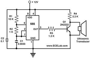
The ultrasonic cleaning machine functions as a humidifier and operates on a simple circuit primarily consisting of an ultrasonic oscillator. It generates ultrasonic frequency signals, typically within the range of 20-40 kHz, using a transistor. These signals are transmitted...
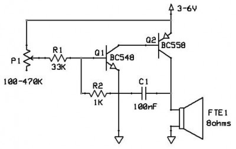
This circuit functions as an oscillator, capable of generating a sound wave or tone. The frequency of the tone, whether high or low, is adjustable via a variable resistor. The volume produced by this circuit is substantial; therefore, it...
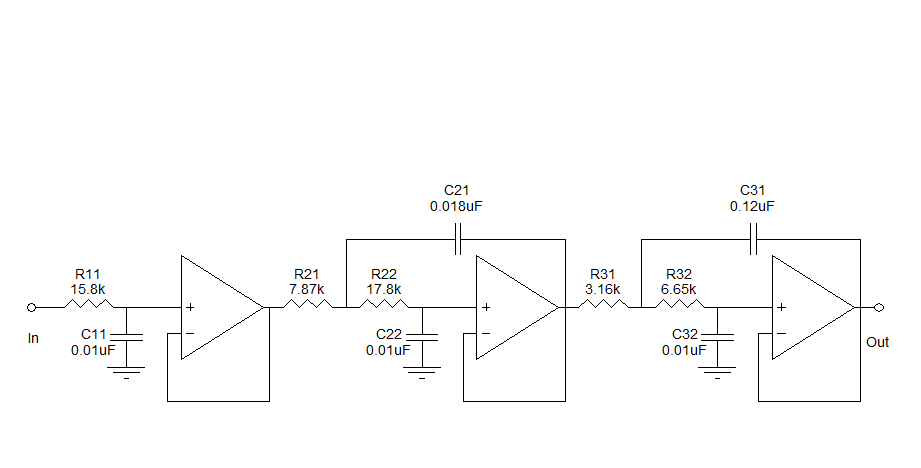
Assistance is needed to understand a schematic. Most components are clear, except for the triangular symbols which are likely operational amplifiers (op-amps). Clarification is required on their implementation and arrangement. The current diagram is intended for testing with a...
The 8051 microcontroller features a transmit channel and a receive channel for serial communication. The transmit data pin (TXD) is designated as P3.1, while the receive data pin (RXD) is located at P3.0. The serial signals on these pins...
Figure 15-22 illustrates a doorbell system that consists of a monostable timing circuit, a password switch, a NAND gate circuit, and a sound output circuit. The operation of the circuit is designed such that when the password switch is...