
Lessons on Electric Circuits Experiments

Digital circuits operate based on binary logic, utilizing signals that are distinctly defined as either low (0) or high (1). The implementation of integrated circuits (ICs), particularly CMOS (Complementary Metal-Oxide-Semiconductor) technology, has revolutionized digital design due to its efficiency and versatility. CMOS technology allows for a wide range of operating voltages, making it suitable for battery-operated devices while maintaining low power consumption, which is critical in modern electronic applications.
When designing circuits with CMOS ICs, it is imperative to understand the importance of static electricity management. The susceptibility of CMOS devices to electrostatic discharge necessitates proper handling techniques, including the use of anti-static materials and grounding methods to prevent damage during assembly.
In practical applications, breadboards serve as an effective platform for prototyping digital circuits. Their design includes power supply rails that streamline the connection of power to various components. This feature is particularly advantageous in digital circuits, which often require multiple power connections for various IC terminals, including those for logic state control and power supply.
A typical example of a simple digital circuit involves connecting a NAND gate IC, which can be represented by the 4011 chip, to input switches and an LED indicator. The NAND gate's output will reflect the logical operation based on the states of the input switches. Incorporating additional switches and indicators, such as an 8-position switch and a 10-segment LED bar graph, enhances the circuit's functionality and allows for scalability in design.
It is essential to consult the datasheet of the 4011 chip for specific pin configurations and operational parameters when assembling the circuit. Understanding the pinout diagrams is crucial for ensuring correct connections and maximizing the performance of the circuit. This knowledge base supports the development of robust digital systems capable of performing complex logical operations and computations efficiently.Digital circuits are circuits dealing with signals restricted to the extreme limits of zero and some full amount. This stands in contrast to analog circuits, in which signals are free to vary continuously between the limits imposed by power supply voltage and circuit resistances.
These circuits find use in "true/false" logical operations and digit al computation. The circuits in this chapter make use of IC, or integrated circuit, components. Such components are actually networks of interconnected components manufactured on a single wafer of semiconducting material. Integrated circuits providing a multitude of pre-engineered functions are available at very low cost, benefitting students, hobbyists and professional circuit designers alike.
Most integrated circuits provide the same functionality as "discrete" semiconductor circuits at higher levels of reliability and at a fraction of the cost. Circuits in this chapter will primarily use CMOS technology, as this form of IC design allows for a broad range of power supply voltage while maintaining generally low power consumption levels.
Though CMOS circuitry is susceptible to damage from static electricity (high voltages will puncture the insulating barriers in the MOSFET transistors), modern CMOS ICs are far more tolerant of electrostatic discharge than the CMOS ICs of the past, reducing the risk of chip failure by mishandling. Proper handling of CMOS involves the use of anti-static foam for storage and transport of IC`s, and measures to prevent static charge from building up on your body (use of a grounding wrist strap, or frequently touching a grounded object).
Circuits using TTL technology require a regulated power supply voltage of 5 volts, and will not tolerate any substantial deviation from this voltage level. Any TTL circuits in this chapter will be adequately labeled as such, and it will be expected that you realize its unique power supply requirements.
When building digital circuits using integrated circuit "chips, " it is highly recommended that you use a breadboard with power supply "rail" connections along the length. These are sets of holes in the breadboard that are electrically common along the entire length of the board.
Connect one to the positive terminal of a battery, and the other to the negative terminal, and DC power will be available to any area of the breadboard via connection through short jumper wires: With so many of these integrated circuits having "reset, " "enable, " and "disable" terminals needing to be maintained in a "high" or "low" state, not to mention the VDD (or VCC) and ground power terminals which require connection to the power supply, having both terminals of the power supply readily available for connection at any point along the board`s length is very useful. Most breadboards that I have seen have these power supply "rail" holes, but some do not. Up until this point, I`ve been illustrating circuits using a breadboard lacking this feature, just to show how it isn`t absolutely necessary.
However, digital circuits seem to require more connections to the power supply than other types of breadboard circuits, making this feature more than just a convenience. To begin, connect a single NAND gate to two input switches and one LED, as shown. At first, the use of an 8-position switch and a 10-segment LED bargraph may seem excessive, since only two switches and one LED are needed to show the operation of a single NAND gate.
However, the presence of those extra switches and LEDs make it very convenient to expand the circuit, and help make the circuit layout both clean and compact. It is highly recommended that you have a datasheet for the 4011 chip available when you build your circuit.
Don`t just follow the illustration shown above! It is important that you develop the skill of reading datasheets, especially "pinout" diagrams, when connecting IC terminals to other circuit elements. The da 🔗 External reference
Related Circuits
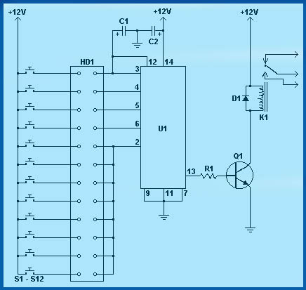
Circuit diagram schematics of electronic keys, electronic locks, digital electronic locks, transistor code locks, and combination electronic locks. The circuit schematics for electronic locking mechanisms encompass a variety of designs tailored to enhance security and convenience in access control systems....
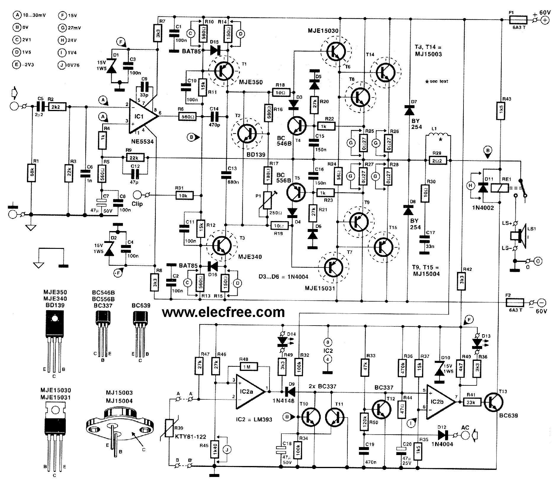
This circuit is designed for friends who are interested in high-power amplifier circuits. It can deliver approximately 300 Watts RMS and operates as an OCL (Output Capacitor-Less) Class AB amplifier, providing high sound power while systematically protecting the loudspeaker...
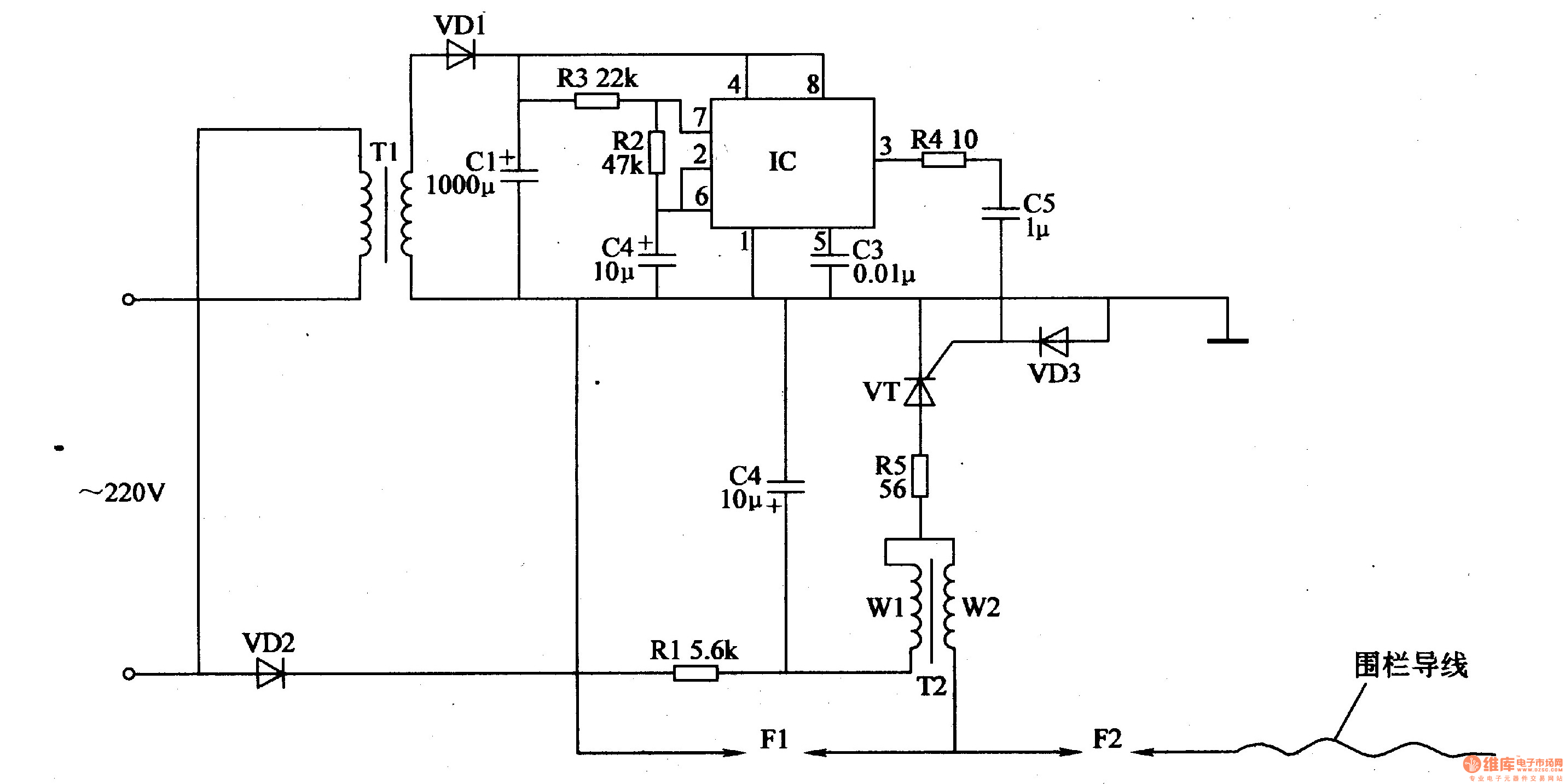
The electric fence control circuit consists of a power supply circuit, a pulse generator, and a high-voltage circuit, as illustrated in Figure 4-27. The power supply circuit includes a power transformer (T1), rectifier diodes (VD1, VD2), filter capacitors (C1,...
Introduction The MIC2290 is an internally compensated standard step-up switching regulator that features an integrated power switch and Schottky diode. The inclusion of these components makes the MIC2290 an optimal solution for 48V Avalanche Photo Diode (APD) applications. In...
This page presents several transistor circuits that are not commonly found on other pages due to the absence of a specific topic. These circuits, however, illustrate particular points but lack detailed descriptions. An example of an RF amplifier circuit...

SM indicates that the tube can produce certain frequencies and discusses the use of TV tubes to achieve improved sound quality at higher frequencies. The effectiveness of this approach can only be determined through experimentation with the specified frequency...