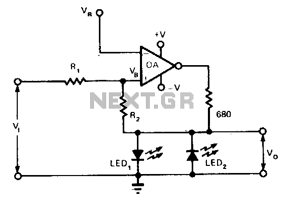
Visual-level-indicator

This indicator functions as a switch with hysteresis characteristics. When the input voltage temporarily or permanently exceeds the highest reference level, LED1 is activated. Conversely, if the voltage drops below the lowest reference level, LED1 turns off and LED2 is activated. The output voltage, V0, is clamped to either the diode voltage VDI or Vm, depending on which LED is conducting. For V0 to be positive, the voltage VB must be positive relative to the reference voltage VR; for V0 to be negative, VB must be negative relative to VR.
The circuit described operates as a voltage comparator with hysteresis, utilizing two LEDs to provide visual feedback regarding the state of the input voltage. The hysteresis feature ensures that the circuit has two distinct threshold levels for switching, which helps to eliminate noise and provides stable operation.
The primary components of the circuit include a voltage reference source, a comparator, and two light-emitting diodes (LEDs). The comparator compares the input voltage (VB) to two reference voltages: the upper threshold and the lower threshold. When the input voltage exceeds the upper threshold, the comparator output changes state, turning on LED1. This indicates that the input voltage is above the acceptable range.
As the input voltage decreases and falls below the lower threshold, the comparator switches off LED1 and turns on LED2, signaling that the input voltage has dropped below the acceptable level. This dual LED configuration provides clear visual indications of the input voltage status.
The output voltage (V0) is determined by the state of the conducting LED. When LED1 is on, V0 is clamped to the diode voltage (VDI), which is typically around 0.7V for silicon diodes. When LED2 is on, V0 is clamped to a different voltage level (Vm), which may be defined by the circuit design.
The relationship between VB and the reference voltage (VR) is crucial for determining the output state. For V0 to be positive, VB must be greater than VR, ensuring that the circuit operates within the desired parameters. Conversely, if VB is less than VR, V0 becomes negative, indicating an undesired condition.
This circuit is particularly useful in applications where voltage monitoring and visual indication are required, such as in power supply systems, battery management systems, and other electronic devices that require reliable voltage thresholds.This indicator is basically a switch with hysteresis characteristics. If the input voltage momentarily (or permanently) exceeds the most positive reference level, LEDl is switched on. If, on the other hand, the voltage falls below the negative, or least positive, reference level, LEDl will be switched off and LED2 switched on.
The output voltage, V0 is clamped either to the diode voltage VDI, or V m depending on which LED is conducting. For V0 to be positive, VB has to be positive with respect to the reference voltage VR; for V0 to be negative, VB has to be negative with respect to VR.