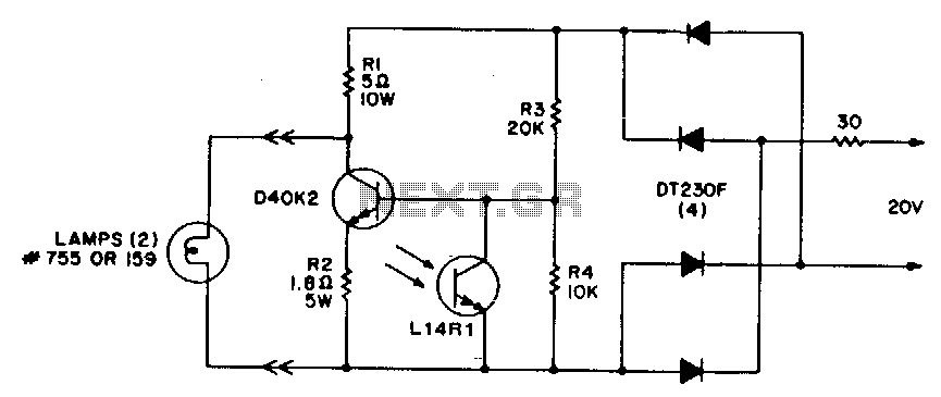
Lighted-display-brightness-control

This circuit offers a cost-effective method for controlling light levels. Power for the circuit is derived from a relatively high source impedance transformer or motor windings, which are typically used to drive low-voltage lamps in these applications. It is important to note that the bias resistors are optimized for a 20-V, 30-0 source and must be recalculated for different sources. The Ll4Rl component is positioned to receive the same ambient illumination as the display and should be shielded from the light emitted by the display lamps. As the ambient light in the room decreases, the illumination level of the lighted displays should also be reduced to prevent undesirable or unpleasant visual effects.
This circuit employs a feedback mechanism to adjust the brightness of lighted displays based on ambient lighting conditions. The primary component of the circuit is the Ll4Rl light-dependent resistor (LDR), which senses the level of ambient light. When the ambient light decreases, the resistance of the LDR increases, leading to a change in the voltage levels in the circuit. This change is detected by a comparator or a microcontroller, which then adjusts the output to the display lamps accordingly.
The power supply requirements dictate the use of a transformer with a high source impedance, which is crucial for the operation of the circuit. The circuit design must consider the impedance characteristics to ensure proper functionality. The bias resistors, which play a vital role in setting the operating point of the circuit, should be calculated based on the specific voltage source being used to maintain optimal performance.
Furthermore, shielding the LDR from direct light emitted by the display lamps is essential to ensure accurate readings of the ambient light levels. This can be achieved through the use of a housing or enclosure that blocks direct illumination while allowing ambient light to reach the sensor. This design consideration helps to prevent feedback loops that could cause the display brightness to fluctuate unnecessarily.
The overall goal of this circuit is to create a comfortable viewing environment by dynamically adjusting the brightness of displays in response to changes in surrounding light conditions. By implementing this low-cost solution, users can enhance the usability of electronic displays while reducing eye strain and improving visual comfort.This circuit provides a very low cost method of controlling light levels. Circuit power is obtained from a relatively high source impedance transformer or motor windings, normally used to drive the low-voltage lamps used in these functions. It should be noted that the bias resistors are optimized for the 20-V, 30-0 source, and they must be recalculated for other sources.
The Ll4Rl is placed to receive the same ambient illumination as the display and should be shielded from the light of the display lamps. The illumination level of lighted displays should be lowered as the room ambient light dims, to avoid undesirable or unpleasant visual effects.