
Lighthouse schematics

The revised schematic incorporates several key components that enhance the functionality and reliability of the lighthouse project. Central to this design is the PIC12F683 microcontroller, which serves as the control unit. This microcontroller is well-suited for low-power applications and offers a range of I/O options, making it ideal for embedded systems.
The schematic includes various peripheral components that support the microcontroller's operation. For instance, a crystal oscillator may be integrated to provide accurate timing, which is crucial for the lighthouse's functionality. Additionally, decoupling capacitors are positioned near the power supply pins of the microcontroller to mitigate noise and ensure stable operation.
Input and output interfaces are also detailed in the schematic. The design likely includes light-emitting diodes (LEDs) to indicate the status of the lighthouse, as well as a relay or transistor circuit to control a larger load, such as a lamp or beacon. The inclusion of resistors for current limiting and pull-up configurations ensures proper operation of the LEDs and switches.
Power management is another critical aspect of the design. The schematic may feature a voltage regulator to provide a stable voltage supply to the microcontroller and other components, ensuring consistent performance even as battery levels fluctuate.
Overall, the combination of the PIC12F683 microcontroller, supporting components, and careful attention to power management and noise reduction creates a robust and efficient design for the lighthouse project. The use of SourceBoost Technologies' BoostC tool suite allows for streamlined programming and debugging, facilitating the development process and enhancing the project's overall effectiveness.I`ve revised the schematic for this project and had a proper PCB made, see the new version here. For anyone who is interested (Hi Richard) here are my project files for the lighthouse project. The project is written for the PIC12f683 using SourceBoost Technologies BoostC that I use as a tool suite in Microchip. 🔗 External reference
Related Circuits
This simple robot responds to light and avoids obstacles without the need for a microcontroller, programmer, or PC. The primary component in the circuit is a window discriminator, which functions as an advanced window comparator. Resistors R1 and R2,...
Because it uses few parts, a printed circuit board is not necessary; components can simply be soldered to one another. However, a box is desirable for operating convenience. The case and aerial from a discarded toy walkie-talkie was used...
The schematics on this page are provided strictly for educational purposes. If anyone intends to use these designs for profit, they are required by law to obtain permission from the legal owner(s) of the design and comply with any...
This circuit is a resonant twin-T filter. Its purpose is to provide a reasonable imitation of a low-pass response, which it achieves effectively. The schematic illustrates two variations: one with self-oscillation and one without. The version built includes oscillation....
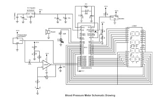
This digital circuit outlines a concept for a digital blood pressure meter that incorporates an integrated pressure sensor, analog signal conditioning circuitry, microcontroller hardware/software, and a liquid crystal display. The sensing system measures cuff pressure (CP) and extracts pulses...
AC power is rectified and applied to the motor in one polarity when the momentary switch is held in one direction, and the polarity is reversed when the motor is held in the reverse direction. The remote car starter...