
LM1800 Stereo Demodulator

The LM1800 is designed to facilitate high-fidelity FM stereo demodulation, making it suitable for various audio applications. The phase-locked loop technology employed allows for accurate recovery of the audio signal from the modulated carrier wave, ensuring minimal distortion and high-quality sound output. The automatic switching feature between stereo and mono modes enhances versatility, allowing the circuit to adapt to different signal conditions without manual intervention.
In the circuit configuration, the composite input signal is carefully managed through the use of decoupling capacitors and adjustable resistors, ensuring that the input levels are optimized for the best performance. The filtering network formed by capacitors C7, C8, and resistor R6 is crucial for removing unwanted frequencies and noise, contributing to the overall sound clarity.
The NE5532 operational amplifiers are well-regarded for their low noise characteristics, making them ideal for audio amplification tasks. The inverting configuration allows for precise control over gain, and the use of load resistors ensures that the output stage is appropriately matched for driving subsequent audio components. The careful selection of feedback and decoupling capacitors further stabilizes the circuit and enhances audio fidelity.
Overall, the design of the LM1800-based FM stereo demodulator circuit exemplifies a well-thought-out approach to achieving high-quality audio performance in a compact and efficient manner. The combination of advanced IC technology and thoughtful circuit design principles provides a robust platform for reliable FM stereo demodulation.LM1800 is an integrated FM stereo demodulator IC which has a number of good features integrated on it which makes it possible to design a high quality FM stereo demodulator system with excellent sound quality. The LM 1800 uses phase locked loop technology to regenerate the 38kHz sub carrier from the composite signal.
The features of LM 1800 are au tomatic stereo/mono switching, wide power supply voltage range, good channel separation, excellent power supply rejection, no coils required, tuning can be done using a POT etc. A very simple and high quality FM stereo demodulator circuit using LM1800 is shown here. Composite input signal is applied to pin1 of the IC through POT R5 and capacitor C5. C5 is a DC decoupling capacitor. R5 can be used to adjust the input signal level. The output of the internal audio amplifier circuit (Pin2) is coupled to the phase detector input through capacitor C6.
Capacitors C8, C7 and resistor R6 forms a filter network. Pin 15 is the control terminal of the 70kHz internal voltage controlled oscillator. The required tuning voltage is given to this pin using Resistor R4 & POT R10. Tuning can be performed by adjusting the POT R10. LED D1 is an indicator LED and R1 is its current limiting resistor. C1 is the threshold filter capacitor. Pin 11 is the pilot monitor output pin. Supply voltage ie, 12V DC is applied to pin 16 of the IC. C4 is a noise bypass capacitor for the internal audio amplifier`s output. Right and left audio outputs are available at pins 5&4 of the LM1800. Next stage of the circuit is a 2 channel driver storage based on NE5532 IC. NE5532 is a dual, internally compensated, low noise op-amp suitable for audio applications. First op-amp inside the NE5532 is used for amplifying the left channel and the second op-amp inside the NE5532 is used for amplifying the right channel. Both of them are wired in the inverting mode with a gain of around 4. R14 & R15 are load resistors. C2 & C3 are DC decoupling capacitors. The left & right load/de-emphasis pins (pins 3 &6) are grounded using 3. 9K resistors (resistors R3 & R2). C11 & C12 are feedback capacitors. C13 & C14 are output DC decoupling capacitors. 🔗 External reference
Related Circuits
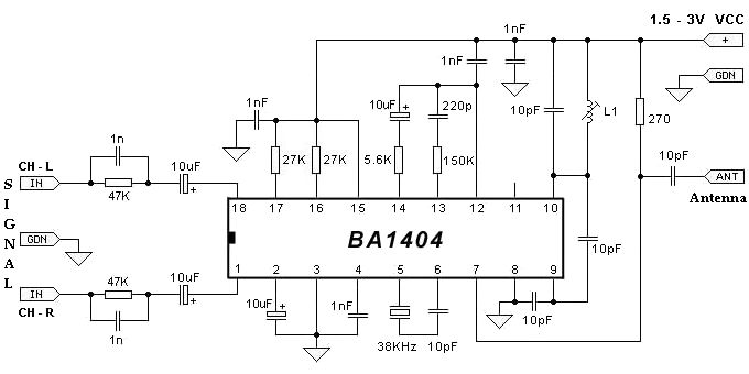
The BA1404 FM stereo modulator IC includes all the necessary components to design a simple, high-efficiency stereo transmitter circuit. It features a stereo modulator that generates composite stereo signals, an FM modulator for creating FM signals, and an RF...
The circuit is designed to provide two channels on a stereo mixer intended for microphones, incorporating a crossfader operation. It utilizes the NE5532 integrated circuit. The stereo mixer circuit features two independent channels, each capable of handling microphone input signals....
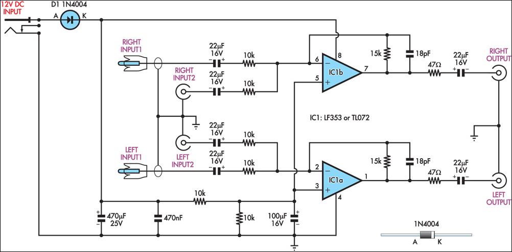
This circuit combines two separate line-level stereo (left and right) signals into a single stereo output, eliminating the need to switch between two sets of input signals. In this application, it is utilized to connect stereo audio from a...
A general purpose audio power amplifier is a must have for the electronics amateur. It's not a good thing to use your HiFi set for an experiment, when there's a risk of blowing its transistor out. Amplifier for your...
The output voltage is = 0.707 x Vin, at the center position. The output voltage is = Vin, at either extreme position. This circuit appears to describe a variable output voltage system, likely utilizing a potentiometer or a similar adjustable...
The AN7415 is a monolithic integrated circuit designed for FM stereo demodulation applications. It operates within a voltage range of 1.6 to 7 V DC, making it suitable for handheld FM radios powered by two AA dry cells. This...