
LM2940CT Sensor Connection

The LM2940CT is a low dropout linear voltage regulator designed to provide a stable output voltage with a maximum dropout of 0.5V at up to 1A load current. This device is particularly suited for applications requiring a regulated voltage supply with minimal input-output voltage differential, making it ideal for battery-operated devices.
In the circuit diagram, the LM2940CT is typically connected to a power source, with input and output capacitors placed according to the manufacturer's recommendations to ensure stability and transient response. The input capacitor, often a 0.1µF ceramic capacitor, is connected close to the input pin to filter high-frequency noise. An additional larger electrolytic capacitor (e.g., 10µF to 100µF) may be added to enhance stability and transient response.
The output capacitor is crucial for maintaining the stability of the LM2940CT. A tantalum or aluminum electrolytic capacitor with a value of at least 22µF is usually connected at the output to ensure proper voltage regulation. The circuit may also include a diode for reverse polarity protection, ensuring that the regulator is safeguarded against incorrect connections.
The storage temperature range for the LM2940CT is typically between -40°C to +125°C, allowing it to operate effectively in a variety of environmental conditions. This feature is particularly beneficial in automotive and industrial applications where temperature fluctuations are common.
Overall, the LM2940CT sensor connection circuit is designed to provide reliable voltage regulation while ensuring protection and stability through appropriate component selection and placement.The following circuit shows about LM2940CT Sensor Connection Circuit Diagram. Features: Internal Power Dissipation, Storage Temperature Range .. 🔗 External reference
Related Circuits
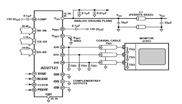
This digital-to-analog converter (DAC) integrated circuit is designed for optimal noise performance, minimizing both radiated and conducted noise. A recommended connection diagram for the ADV7123 is depicted in the following schematic diagram. According to the ADV7123 datasheet, this device...
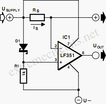
The most effective method for measuring current in a circuit is to insert a sense resistor into the current path. A higher resistance results in a more accurate measurement; however, it can also impact the circuit's operation. Utilizing an...
Scopeclock is a user-friendly hardware device designed to enhance the functionality of X-Y capable analog oscilloscopes. This hardware allows for the conversion of an analog oscilloscope into a scope clock. The project was developed by a team at CEDT...
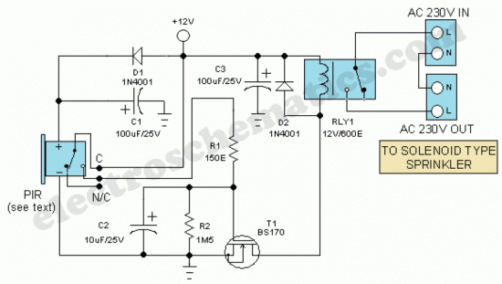
The motion sensor switch circuit is a motion sensor-controlled automatic water sprinkler, but an alarm or light function can be easily added as well. The motion sensor switch circuit utilizes a passive infrared (PIR) sensor to detect motion within...
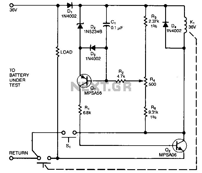
The sensing circuit quickly disconnects the battery voltage and load when the voltage falls below a predetermined threshold. The one-way operation ensures that the circuit does not reconnect the load if the voltage subsequently rises above the threshold. Component...
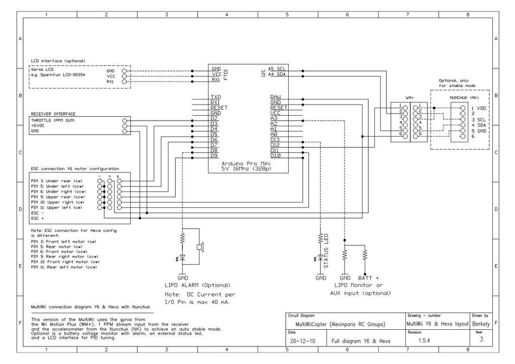
This is a video showcasing a test flight of the Quad Rotor Observer (QRO) v8, which is equipped with the FCWii board, Wii Motion Plus gyroscopes, and Nunchuk accelerometers. The Quad Rotor Observer (QRO) v8 is an advanced quadcopter designed...