
LM3552 white LED driver circuit design

The LED driver circuit utilizes the LM3552, a specialized LED driver IC designed for efficient operation in both torch and flash modes. The primary function of the circuit is to provide a stable and adjustable output current to drive high-brightness LEDs. The circuit requires a DC power supply that can deliver a voltage within the specified range of 2.7V to 5.5V, ensuring compatibility with various LED configurations.
The connection points, including Vin, GND, and the T/F header, are critical for the proper functioning of the circuit. The T/F jumper plays a significant role in determining the operational mode of the LM3552. By connecting the T/F pin to GND, the device is set to torch mode, which is ideal for applications requiring a constant light output at a lower current. In this mode, the LED operates at approximately 200mA, providing an efficient and sustained illumination.
To switch to flash mode, the T/F jumper must be moved to connect the '+' pin to the T/F pin. In this configuration, the LED can draw a higher current of about 700mA, suitable for short bursts of high-intensity light. It is important to note that the internal time-out feature of the LM3552 will automatically disable the flash mode after approximately 1 second to prevent overheating or damage to the LED.
The enable (EN) pin is designed with an internal pull-down resistor, ensuring that the LM3552 remains in a low-power shutdown state by default. This feature is particularly useful for battery-operated devices, as it helps conserve power when the LED is not in use. However, the T/F pin does not have any pull-up or pull-down resistors, which means that if it is left unconnected, the operational mode of the LM3552 becomes indeterminate. Users must ensure proper connections to avoid unexpected behavior in the circuit.
Overall, this LED driver circuit offers versatility and efficiency for driving LEDs in various applications, from constant illumination in torch mode to high-intensity lighting in flash mode. Proper understanding of the connections and operational modes is essential for effective implementation in electronic projects.For this led driver electronic project you will need a DC power supply circuit that provide an output voltage between 2. 7V and 5. 5 volts ( supply voltage must be applied between Vin and GND. The T/F jumper connects the T post to the middle post of the T/F header strip. This connects GND to the T/F pin of the LM3552, placing the part into the 2 00mA torch mode when the part is enabled. When these connections are all made correctly, the Flash LED will be OFF. Setting the EN jumper to the ON position will enable the part and turn on the flash LED. In torch mode, the LED current will be set to approximately 200mA. Placing the T/F jumper across the `+` pin and the T/F pin enables flash mode. The total current delivered to the LED is approximately 700mA. If this jumper is left in flash mode, the internal time-out circuit will disable the switcher after approximately 1 second. The EN pin has an internal pull-down resistor placing the part in shutdown by default and the T/F pin does not have a pull-up or pull-down resistor.
If left unconnected, it is unknown as to whether the LM3552 is in torch or flash mode. 🔗 External reference
Related Circuits

An input sine wave applied to the left amplifier base results in the collector output fluctuating above or below 6.6 volts. The amplifier amplifies and inverts the signal, maintaining a roughly centered output, thereby minimizing the chances of clipping....
This presence detector or proximity sensor circuit responds to the presence of any conductive object, including humans. The sensitivity can be adjusted with potentiometer P1, which is positioned at a considerable distance from the rest of the circuit. This...

The circuit utilizes a KD-9300 music IC, which activates when the button switch (SB) is pressed, causing the electric lamp (E) to light up for approximately 20 seconds before automatically turning off. The setup includes a half-wave rectifier and...

The AC power supply voltage is normal, and a relay is connected to the load (Rfz) circuit. In the event of a load short-circuit failure, the voltage across relay KA drops rapidly, causing KA to release and disconnect the...
Measuring the temperature of coffee is important because the taste of coffee relies on two main factors: the strength of the coffee and its temperature. Measuring the temperature of coffee can be accomplished using a simple electronic circuit designed to...
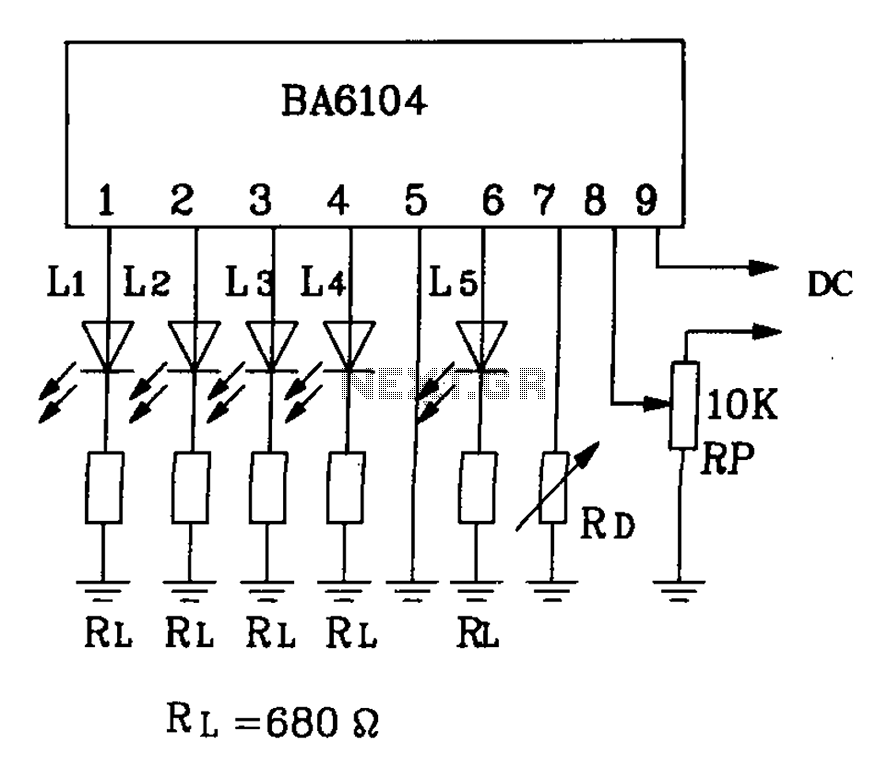
BA6104 is a five-digit LED level meter driver integrated circuit (IC) that features a basic application circuit. The input stage employs a PNP transistor with a composite base input, resulting in high input impedance. The output stage is configured...