
LOGIC DESIGNER

The logic designer serves as a versatile platform for testing and evaluating digital circuits. It comprises various building blocks that can be interconnected to form different configurations, enabling users to create a range of counting and testing stages. The modular nature of the design allows for extensive customization, making it suitable for educational purposes, prototyping, and experimentation.
The primary focus of the logic designer is to facilitate the testing of digital circuits, which includes components such as logic gates, flip-flops, counters, and multiplexers. Each of these components can be represented on the board, allowing for a hands-on approach to learning and understanding digital logic principles. The interconnectivity of these blocks means that users can explore various logical operations and configurations, leading to a deeper comprehension of digital circuit behavior.
Key features of the logic designer include a user-friendly interface that allows for easy manipulation of the building blocks, clear labeling for each component, and the ability to visualize connections in real-time. This setup not only aids in the testing process but also provides immediate feedback on circuit functionality. Additionally, the board is designed to accommodate various power supply options, ensuring compatibility with different digital components.
It is important to note that the logic designer is exclusively intended for digital circuits. As such, it will not provide meaningful results when used with analog devices, such as audio amplifiers or radio frequency circuits. Users should focus on digital logic applications to fully leverage the capabilities of the logic designer. This specialized design ensures that the unit remains a focused and effective tool for testing and learning within the realm of digital electronics.The logic designer is filled with features. It would not be possible to list all the possible combinations of the unit as the various building blocks on the board can be interconnected to obtain a wide variety of counting and testing stages. You will be able to see what we mean after you build the project and start to interconnect the blocks yourself.
But we can give an outline of some of the features we have specially incorporated into the board. You can consider the DESIGNER as a piece of test equipment. It is specially designed for testing digital circuits. In fact it will only test digital circuits. So don`t expect to get any results from an audio amplifier or radio. The type of digital ci 🔗 External reference
Related Circuits

The schematic below illustrates four methods of controlling a relay with a digital logic signal. Figure A can be used in most cases where the relay coil requires 100 mA or less and the input current is 2 milliamps...
This circuit is a Logic Probe that indicates the logic state of any TTL logic circuit node. To operate, the probe must be supplied with the same power as the circuit being analyzed, including the same Vcc and GND....
The 5 volt regulated power supply for TTL and 74LS series integrated circuits has to be very precise and tolerant of voltage transients. These ICs are easily damaged by short voltage spikes. A fuse will blow when its current...
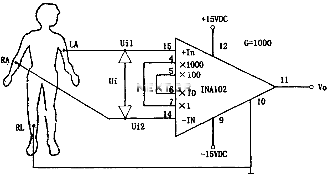
This document outlines a preamplifier circuit designed for measuring human biological signals, such as ECG and EEG. These biological signals are typically weak and require high amplification circuits. The circuit utilizes a low-power integrated operational amplifier, INA102. The INA102...
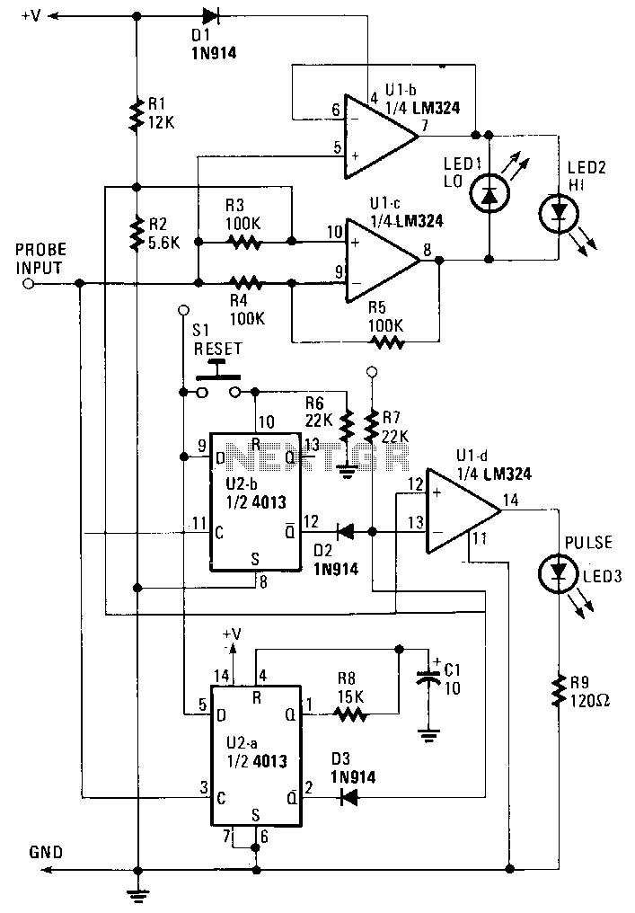
The probe operates using the power supply from the circuit under test (CUT). The input at the probe tip is divided into two pathways. One pathway directs the signal to the clock inputs of U2a and U2b. The other...
There are two switches: a memory disable switch and a pulse polarity switch. The memory disable switch is a push-button that resets the memory to a low state when pressed. The pulse polarity switch is a toggle switch that...