
low cost intercom

The intercom circuit features a 3-stage amplifier design that utilizes resistor-capacitor (RC) coupling to enhance audio signal fidelity while minimizing noise. The initial stage involves transistors T1 and T2 configured to operate as an astable multivibrator. When the user presses the ring button S2, the circuit transitions into a state that generates a ringing signal, effectively alerting the recipient of an incoming call. The generated signals are subsequently amplified by transistor T3, which is responsible for driving the earpiece speaker, ensuring that the audio output is loud enough for clear communication.
The low current consumption of 10 to 15 mA allows for extended battery life, making the intercom system practical for everyday use. The choice of a 9-volt PP3 battery provides sufficient voltage to power the circuit while maintaining efficiency.
For two-way communication, two identical intercom units can be employed, with each unit's output directly feeding into the speaker of the opposite unit. This design facilitates bidirectional audio transmission, allowing both parties to communicate effectively. In a single-battery configuration, connecting the corresponding supply and ground terminals of both units is essential to ensure a stable power source for both amplifiers.
The compact nature of the circuit allows it to be housed within a plastic casing, such as that of a toy cellphone. This not only provides a protective enclosure for the electronic components but also enhances the aesthetic appeal of the intercom system, making it suitable for various applications. Overall, this intercom circuit design is an efficient, cost-effective solution for creating reliable two-way communication systems.This is a design circuit for intercom circuit. The circuit comprises a 3-stage resistor-capacitor coupled amplifier. When ring button S2 is pressed, the amplifier circuit formed around transistors T1 and T2 gets converted into an asymmetrical astable multivib-rator generating ring signals. These ring signals are amplified by transistor T3 to drive the speaker of earpiece. This design circuit is a low cost. This is the figure of the circuit. Current consumption of this intercom is 10 to 15 mA only. Thus a 9-volt PP3 battery would have a long life, when used in this circuit. For making a two-way intercom, two identical units, as shown in figure, are required to be used. Output of one amplifier unit goes to speaker of the other unit, and vice versa. For single-battery operation, join corresponding supply and ground terminals of both the units together. The complete circuit, along with microphone and earpiece etc, can be housed inside the plastic body of a cellphone toy, which is easily available in the market.
🔗 External reference
Related Circuits
The recent availability of a broad line of truly high-performance consumer integrated circuits makes it possible to construct a high-quality, low-noise, low-distortion electronic system. The emergence of advanced consumer integrated circuits has significantly transformed the landscape of electronic design, enabling...
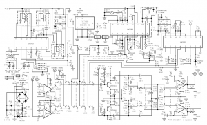
The Wien-bridge sine-wave oscillator utilizes a light bulb for amplitude stabilization. The circuit depicted in Fig 1 omits the light bulb and incorporates several enhancements that reduce distortion and produce a test signal sufficiently pure for evaluating modern operational...
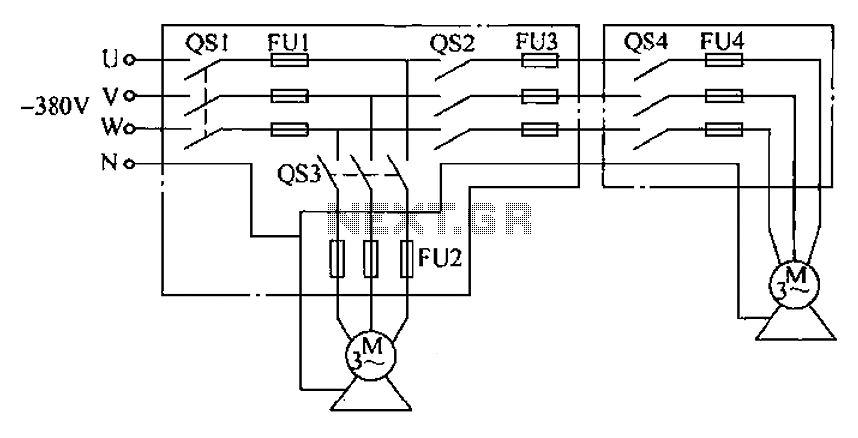
The agriculture and electrical power harrow plow power cord must consist of four rubber cables, with one core wire designated as the ground wire. The traction machine housing must be properly grounded. The two traction power machines are connected...
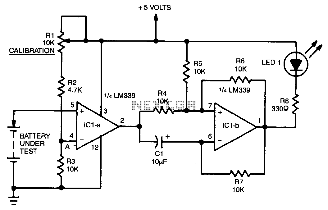
A voltage divider consisting of R1, R2, and R3 is utilized to establish the input reference voltage below which the batteries should be replaced. The reference voltage at point A is adjustable via R1. As illustrated in the diagram,...
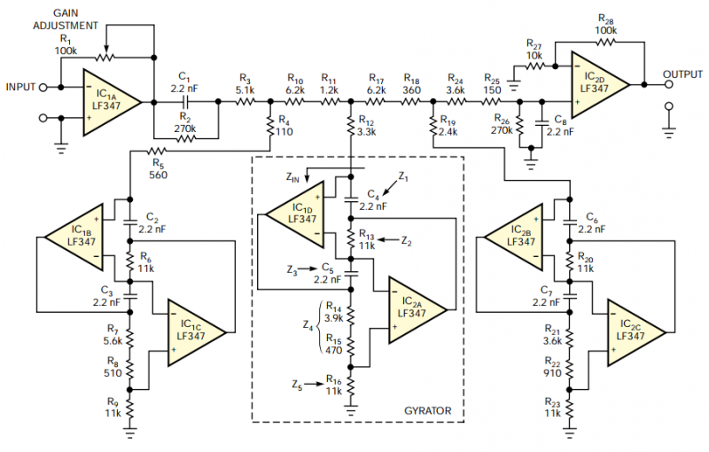
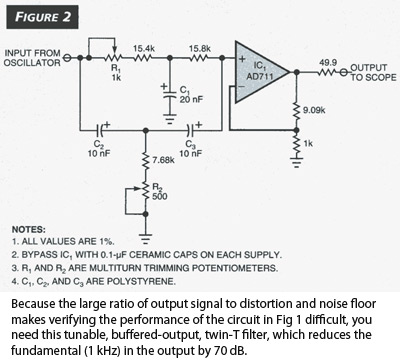
The filter should provide adjustable gain to maximize SNR at the audio processor's first stage. The filter's frequency response should also include a notch at 19 kHz to achieve maximum attenuation at the FM-subcarrier pilot-tone frequency and thus minimize...
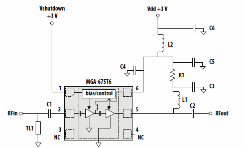
This application note discusses the use of Avago Technologies' MGA-675T6 for 5-6 GHz applications. The MGA-675T6 is internally integrated with shutdown and biasing circuitry, which simplifies the external circuitry. The shutdown feature allows the low noise amplifier (LNA) to...