
LOW COST LASER DIODE DRIVER

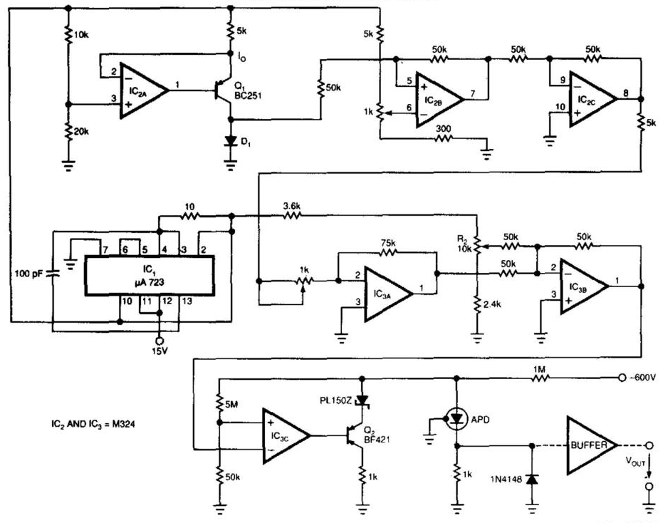
The laser diode driver circuit is particularly designed for applications requiring precise temperature control and stable current supply to the laser diode. The core components include the laser diode module, which features an integrated monitor photodiode that provides feedback on the optical output, allowing for real-time monitoring of the laser's operational status. The use of a thermoelectric cooler (TEC) is crucial for maintaining optimal operating temperatures, especially in environments where thermal fluctuations could lead to performance degradation or damage to the laser.
The constant-current source configuration ensures that the laser diode receives a steady current, thereby preventing fluctuations that could lead to instability in the laser output. The current limiting feature, implemented through resistor R2, protects the laser diode from overcurrent conditions, which could otherwise lead to failure. The adjustment of the operating point via resistor R3 allows for fine-tuning of the laser output, ensuring that it meets the specific requirements of the application.
The feedback mechanism involving the TEC is vital for effective thermal management. The comparator circuit continuously monitors the temperature of the laser diode and adjusts the TEC operation accordingly. When the temperature exceeds the predefined set point, the TEC is activated to cool the laser, thereby stabilizing its performance. The ability to adjust the temperature set point via resistor R16 provides flexibility for various operational conditions, making this circuit suitable for a wide range of applications in laser technology. Overall, this laser diode driver circuit exemplifies an efficient design approach that combines safety, stability, and adaptability for high-performance laser applications.The circuit presented is a low-cost laser-diode driver with current limiting and a lasing monitor for safe operation of the laser. The driver provides temperature stabilization using a built-in thermoelectric-cooler (TEC) controller.
This circuit is designed around a QLM5S876 1. 55-m laser-diode module with a built-in monitor photodiode, TEC, and t hermistor. The laser is driven by the constant-current source Q2 and Q1. The drive current is stabilized against supply changes by Z1, limited by R2, and adjusted by R3 to the desired operating point. When the current is small, the laser doesn`t lase and the monitor photodiode detects no optical power.
As a result, comparator U1C goes below its trip point and LED1 turns off. When the current is adjusted and passes the laser threshold, sufficient optical power is generated by the laser, causing photo current to flow through the photodiode and the comparator to drive the lasing monitor indicator LED1 to on. The TEC controller circuit is a feedback system. If the temperature is higher than the set point, the comparator output will be high and will drive the TEC element through R15, Q3, and Q4.
The TEC drive current is limited by Z2. When the TEC is driven on, it cools the laser. This increases the voltage of the inverting output until it passes the comparator`s upper trip point and turns off the TEC`s drive current. The temperature set point can be adjusted by R16. 🔗 External reference
Related Circuits
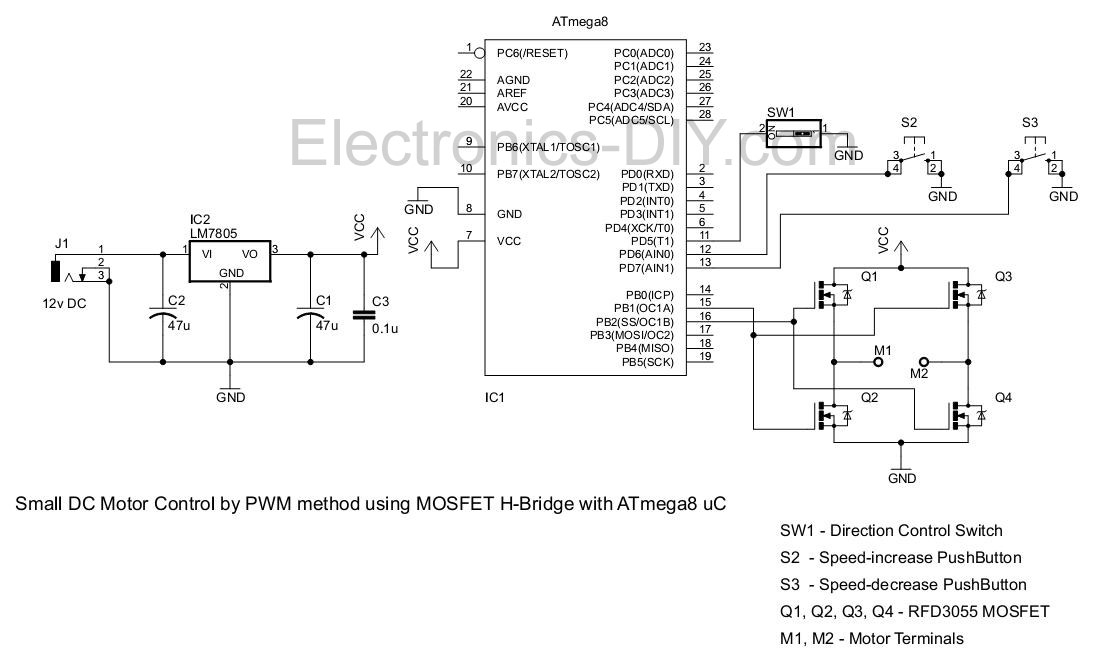
This project involves controlling a small DC motor, sourced from an old personal cassette player, using the ATmega8 microcontroller. The ATmega8 features three PWM channels, of which two are utilized in this application. The PWM signals are sent to...
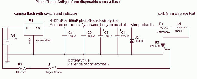
This is a fun and non-dangerous project for those people who like to throw projectiles magnetically. It simply works by placing a ferromagnetic projectile at one end of a coil and pulsing some power in it. The trick is...
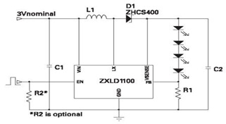
The ZXLD1100 is a PFM flyback DC to DC boost converter that operates in discontinuous mode. The following circuit diagram illustrates the configuration of four LED drivers for handset LCD backlighting using this device. The ZXLD1100 is designed to...
Laser-receiver circuits must bias their avalanche photodiodes (APD) to achieve optimal gain. Unfortunately, an APD's gain depends on the operating temperature. The circuit controls the operating voltage of an APD over a large temperature range to maintain the gain...
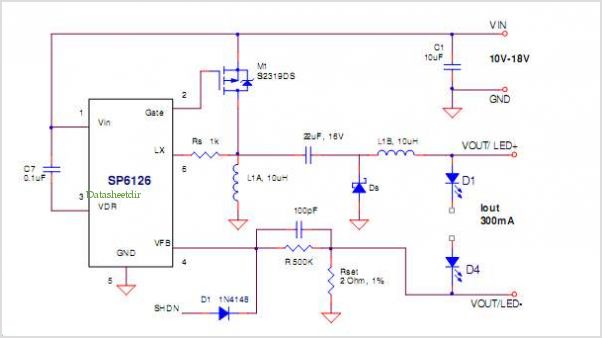
The SP6331, SP6333, and SP6335 are quad power supervisory circuits designed for microprocessor reset applications, featuring multiple reset voltage options. This family of devices offers low voltage monitoring capabilities for up to four supply voltages, with two precision factory-set...
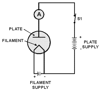
The diode tube under examination is essentially Edison’s early incandescent bulb containing a plate. The term "diode" refers to the two elements or electrodes within the glass container that constitute the tube. Shortly after the discovery of the Edison...