
Low Cost Phone Battery Charger Schematic Diagram

This low-cost phone battery charger circuit is designed to provide an efficient and economical solution for charging mobile phone batteries. It operates at a voltage of 7.2 volts, making it suitable for various types of mobile phones and battery packs that operate within this voltage range.
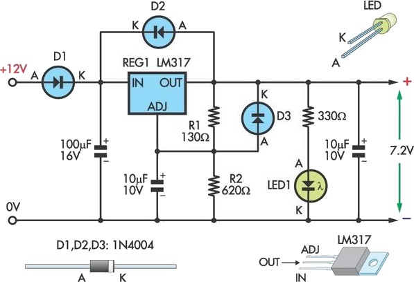
The circuit typically consists of a transformer, a bridge rectifier, a voltage regulator, and some passive components such as resistors and capacitors. The transformer steps down the AC mains voltage to a level suitable for charging. The bridge rectifier converts the AC voltage to DC, which is necessary for charging the battery.
A voltage regulator is employed to ensure that the output voltage remains stable at 7.2 volts, preventing overcharging and potential damage to the battery. Additional components may include diodes for reverse polarity protection and capacitors to smooth out any fluctuations in the output voltage.
This charger circuit can be constructed using readily available components, making it accessible for hobbyists and engineers looking for a cost-effective charging solution. Proper attention to safety and adherence to electrical standards is crucial when assembling and using this circuit to ensure reliable operation and user safety.Mobile phone, phone battery chargers on hand wearing the souk are quite expensive. This circuit presented at juncture comes so a low-cost alternative to charge cellular phone telephones/battery packs with a rating of 7. 2 volts. You are reading the Circuits of Low Cost Phone Battery Charger And this circuit permalink url it is 🔗 External reference
Related Circuits
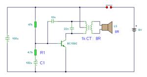
The simple bell circuit without IC. It includes a doorbell circuit that can produce different sounds using integrated circuits, transistors, and resistors. The circuit utilizes a coded trigger mechanism to differentiate between various visitors. When the button is pressed,...
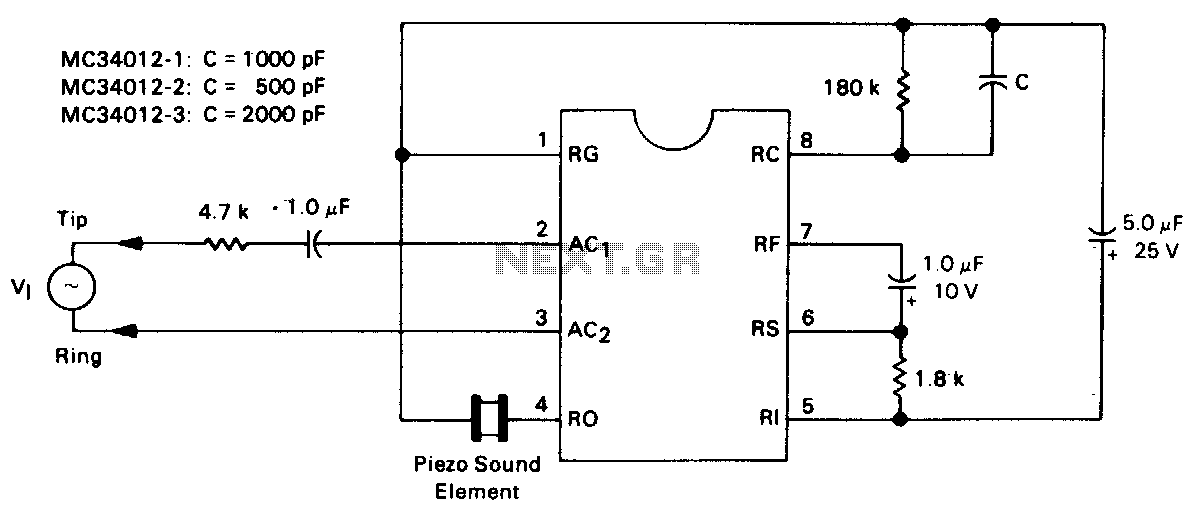
This is a complete telephone bell replacement circuit with minimal external components, featuring an on-chip diode bridge and transient protection, along with direct drive for piezoelectric transducers. The telephone bell replacement circuit is designed to efficiently replace traditional mechanical bells...
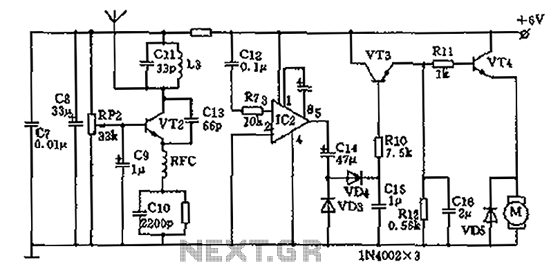
The homemade wireless remote control circuit diagram illustrates a motor remote control transmitter circuit. The circuit utilizes a 555 timer along with resistors R1, R2, RP1, diodes VD1, VD2, and capacitor C1 to create a variable duty cycle astable...
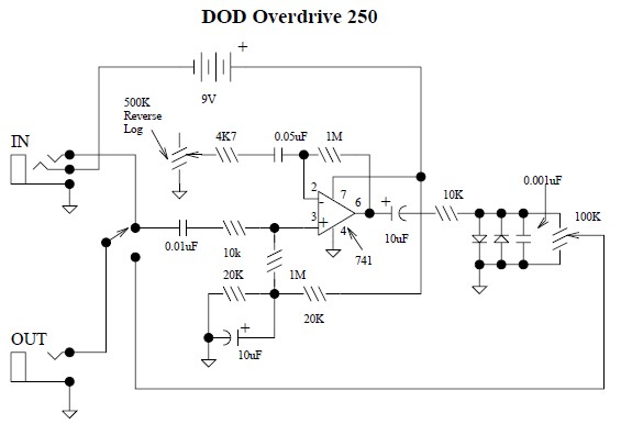
This document provides a circuit diagram for the DOD Overdrive 250 preamp. The DOD Overdrive 250 is similar to the MXR Distortion Plus and several other devices, utilizing a 741 operational amplifier with two diodes on the output channel....
This circuit allows an external 12V SLA battery to power a camcorder that typically uses a built-in 7.2V battery. Obtaining such batteries for older camcorder models can be challenging and costly. The circuit utilizes a standard LM317 adjustable voltage...
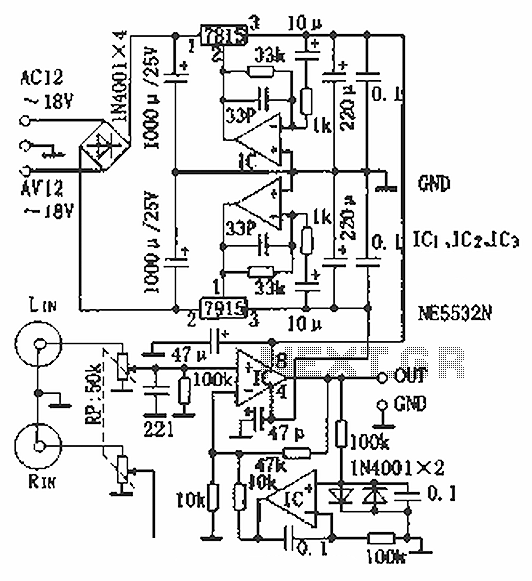
Hi-fi headphones possess a wide frequency response and low distortion, making them incomparable to desktop Hi-Fi audio systems, particularly when compared to some branded headphones and even high-quality speakers. High-fidelity headphones are designed for music listening, offering high resolving...