Low-power-switching-regulator

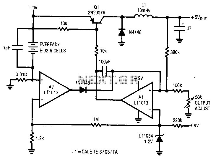
A simple battery-powered switching regulator provides 5 V output from a 9-V source with 80% efficiency and a 50 mA output capability. When Q1 is activated, its collector voltage increases, allowing current to flow through the inductor. This causes the output voltage to rise, which in turn increases the output of A1. Once the output reaches a certain level, Q1 turns off, and the output voltage decays through the load. The 100-pF capacitor ensures clean switching. The cycle repeats when the output voltage drops low enough for A1 to activate Q1 again. The 1-µF capacitor ensures low battery impedance at high frequencies, preventing voltage sag during switching.
The described circuit is a basic switching regulator designed to convert a higher input voltage (9 V) into a stable lower output voltage (5 V) with a specified efficiency of 80%. The regulator is capable of delivering up to 50 mA of output current, making it suitable for low-power applications.
The operation of the circuit is primarily controlled by transistor Q1, which acts as a switch. When Q1 is turned on, it allows current to flow through the inductor, storing energy in its magnetic field. As the inductor charges, the output voltage increases. This voltage is monitored by operational amplifier A1, which serves as a feedback mechanism. When the output voltage reaches a predetermined level, A1 signals Q1 to turn off, interrupting the current flow through the inductor.
The decay of the output voltage occurs as the energy stored in the inductor is released through the load. This process is crucial for maintaining the desired output voltage. The inclusion of a 100-pF capacitor in the circuit is essential for ensuring clean transitions during the switching process, minimizing voltage spikes and noise that could affect the performance of the regulator.
To maintain stable operation, especially under varying load conditions, a 1-µF capacitor is employed to provide low impedance at high frequencies. This capacitor helps to stabilize the voltage during rapid changes in current demand, preventing any significant dips or 'sags' in output voltage that could occur during the switching events.
Overall, this switching regulator design exemplifies an efficient method for voltage conversion in battery-powered applications, utilizing feedback control and energy storage components to achieve a reliable output.A simple battery-powered switching regulator provides 5 V outfrom a 9-V source with 80% efficiency and 50 mA output capability. When Q1 is on, its collector voltage rises, forcing current through the inductor. The output voltage rises, causing A1"s output to rise. Q1 cuts off and the output decays through the load. The 100-pF capacitor ensures clean switching. The cycle repeats when the output drops1ow enough for A1 to turn on Ql. The 1-~