
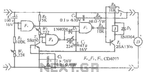
low power voltage doubler booster

A voltage doubler is a circuit that converts a lower input voltage to a higher output voltage, effectively doubling the input voltage. This is achieved through the use of capacitors and diodes, which work together to store and transfer energy. In a typical voltage doubler configuration, the circuit is composed of two diodes and two capacitors. The first diode allows current to flow into the first capacitor during the positive half-cycle of the input AC signal, charging it to the peak voltage of the input. During the negative half-cycle, the second diode becomes forward-biased, allowing the charge from the first capacitor to be combined with the input voltage, thereby doubling the output voltage across the second capacitor.
The design of a voltage doubler circuit must consider several factors, including the load current, the frequency of the input signal, and the characteristics of the components used. The capacitors should be rated for a voltage higher than the expected output to ensure reliability, and the diodes must have a low forward voltage drop to maximize efficiency. Additionally, the output ripple voltage should be minimized to provide a stable DC output, which may require the use of filtering techniques.
When implementing a voltage doubler in miniature electronic devices, it is crucial to ensure that the circuit does not exceed the power ratings of the components, as overheating can lead to failure. Furthermore, the overall size of the voltage doubler circuit should be considered to maintain the miniaturization objective of the device. By effectively integrating a voltage doubler, designers can enhance the performance of battery-operated miniature devices without compromising their size or functionality.All miniature electronic devices operate off batteries. Some of them need higher than the standard battery voltages to operate efficiently. If the battery of that specific voltage is unavailable, we are forced to connect additional cells in series to step up the DC voltage. Thus, the true meaning of miniaturisation is lost. A simple way to overcome this problem is to employ a voltage doubler, if the device under consideration can operate at a small current..
🔗 External reference
Related Circuits
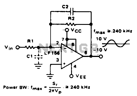
Parasitic input capacitance (ICi) is 3pF for LM5S, LF156, and LF157, along with any additional layout capacitance. This interacts with the feedback element and creates undesirable high-frequency effects. To mitigate this, a capacitor (C2) should be added in conjunction...
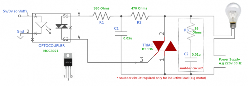
For many years, electromagnetic relays have been utilized as switches for controlling high-voltage devices. However, due to their large size and the noise they produce (both electrical and mechanical), TRIACs combined with opto-couplers have emerged as a more effective...
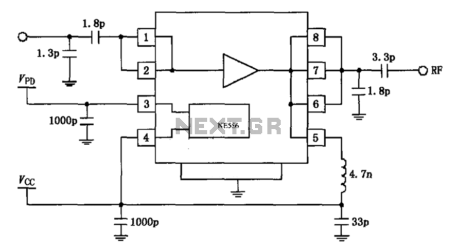
The circuit depicted in the figure is based on the RF2126, a 2450 MHz end-stage linear power amplifier. The radio frequency (RF) signal enters through input pin 1 and is subsequently amplified by the amplifier stages (pins 5, 6,...
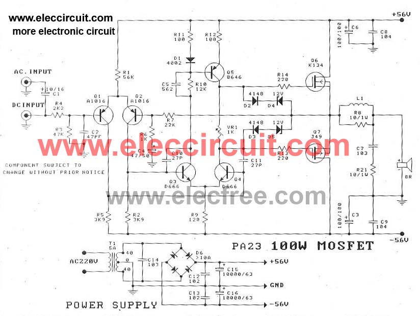
This circuit is a MOSFET power amplifier configured in an OCL (Output Capacitor-Less) topology. It delivers an output power of 100 watts and can utilize MOSFETs such as K134 and J49 or J162 and K1058. When driving an 8-ohm...
A schematic diagram of the high-voltage power supply recommended for use with the power transformer. This power supply can also be used for other equipment with similar requirements. CAUTION: hazardous high voltages. The high-voltage power supply schematic is designed to...
The "R-h sampling circuit limit order" aims to reduce the sampling resistor. A DC voltage level can be positioned between the components. The circuit includes a line amplifier that allows for magnification adjustments and is designed to protect against...