
Low ripple power supply

The described circuit is designed to meet the demands of high current applications while ensuring minimal ripple voltage, which is crucial for the fidelity of audio signals in Class AB amplifiers. The Darlington transistor configuration formed by Q1 and Q2 provides high current gain, allowing the circuit to drive larger loads efficiently. The selection of ZD1 is critical; it should be set to provide a stable reference voltage that compensates for the base-emitter voltage drop of Q1, ensuring proper biasing of the transistor.
R1 works in conjunction with ZD1 to set the desired operating point of Q1, influencing the overall performance of the amplifier. The choice of C2 is particularly important as it directly affects the output ripple voltage. By selecting a larger capacitance value, the circuit can achieve smoother output by effectively filtering out fluctuations in voltage. The calculated effective capacitance of 37,000 µF, when using a 100 µF capacitor for C2, illustrates the significant impact of the transistor gains on the overall capacitance, providing a robust solution for high-performance audio applications.
In summary, this circuit design is well-suited for high-current, low-ripple voltage applications, particularly in audio amplification, where sound quality is paramount. The careful selection of components, especially the reference voltage and capacitance, plays a vital role in ensuring optimal performance and reliability of the amplifier.This circuit may be used where a high current is required with a low ripple voltage (such as in a high powered class AB amplifier when high quality reproduction is necessary), Ql, Q2, and R2 may be regarded as a power darlington transistor. ZDl and Rl provide a reference voltage at the base of Ql. ZDl should be chosen thus: ZDl = Von-1 C2 can be chosen for the degree of smoothness as its value is effectively multiplied by the combined gains of Q1/Q2, if 100 µF is chosen for C2, assuming minimum hfe for Ql and Q2, C = 100 x 15(Q1) x 25(Q2) = 37,000 µf.
Related Circuits
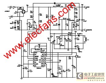
The FAN4810 operates as a continuous conduction mode (CCM) power factor correction (PFC) controller. It features an internal safety detection mechanism that prevents circuit malfunction due to component damage. The device has a power-handling capability of up to 1A,...
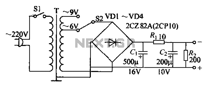
The adjustable current power supply circuit operates at 6V and 9V, utilizing a minimal number of components, which facilitates easy assembly. The circuit can deliver an adjustable output current of up to 100mA, serving as a suitable alternative to...
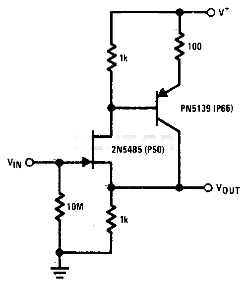
The 2N5485 features low input capacitance, making this compound series-feedback buffer a wide-band unity gain amplifier. The 2N5485 is a field-effect transistor (FET) that is often utilized in applications requiring low noise and high input impedance. Its low input capacitance...
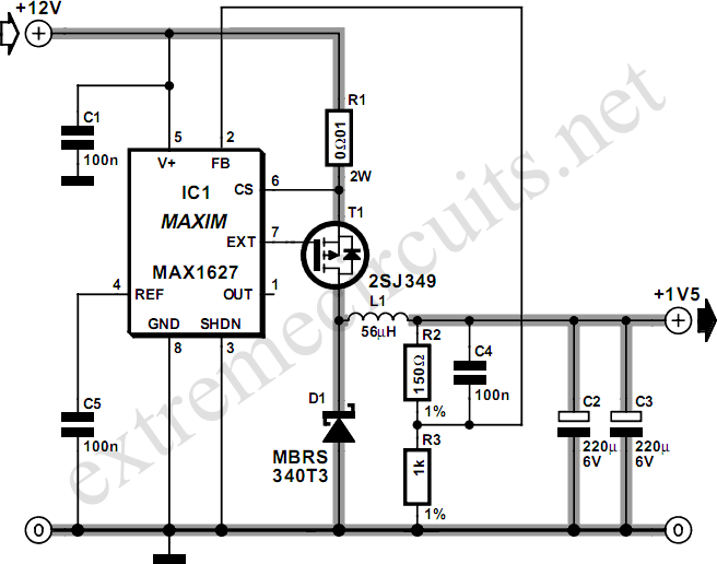
Most small internal combustion engines used in model building utilize glow plugs for starting. However, glow plugs operate at 1.5 V, while components like fuel pumps, starter motors, and chargers typically operate at 12 V. This discrepancy necessitates a...
This compact amplifier is built around the TDA2003 integrated circuit, which can deliver 4W RMS at a 4-ohm load. The TDA2003 offers enhanced performance while maintaining the same pin configuration as the TDA2002. It retains the advantageous features of...
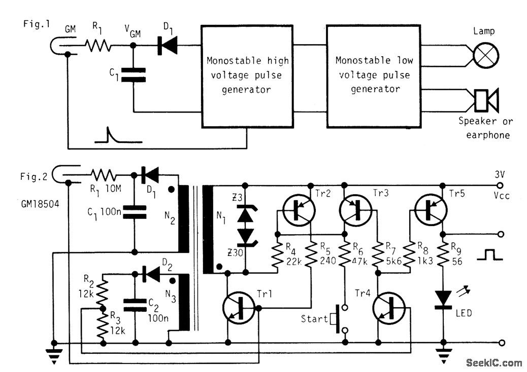
In the absence of radiation, no current is drawn. At normal background radiation levels, the power consumption is extremely low. The instrument may be left on for several months without changing batteries. In this way, the detector is always...