
low volt led flasher schematics

The Joule Thief is a simple and efficient circuit designed to extract energy from low-voltage sources, such as single-cell batteries, and boost it to a higher voltage sufficient to power an LED. The circuit primarily consists of a toroidal inductor, a transistor (commonly the 2N3904), a resistor, and an LED.
In this circuit, the ferrite toroid serves as an inductor, which is crucial for energy storage and transfer. The winding of the toroid creates a magnetic field when current flows through it. The connection at the top of the toroid to the positive terminal of the battery establishes the power supply. The two additional leads from the toroid connect to the resistor and the transistor. The resistor is typically used to limit the base current flowing into the transistor, ensuring it operates within safe limits.
The transistor, specifically the 2N3904, is a bipolar junction transistor (BJT) that functions as a switch in this configuration. The emitter, represented by the arrow in the schematic, is connected to ground, while the collector is linked to the LED. The base, which controls the transistor's operation, receives the signal from the toroid through the resistor. When the circuit is powered, current flows from the battery through the toroid, inducing a magnetic field that causes the transistor to switch on and off rapidly. This oscillation allows energy to be transferred to the LED, producing light.
The LED in the circuit is polarized, meaning it has a specific orientation. The flat side and shorter lead indicate the cathode, which must be connected to the lower potential side of the circuit. The correct connection of the LED is essential for its operation, as reversing the polarity may damage the component.
Overall, the Joule Thief circuit exemplifies the principles of inductive energy transfer and transistor switching, making it an effective solution for utilizing low-voltage power sources efficiently.In the circuit diagram for the Joule Thief, the common point of the toroid is the connection at the top of the hand-wound ferrite toroid, in the upper right of the diagram. This goes to the positive end of the battery. The other two wires from the toroid go to the resistor and to the intersection of the transistor with the LED.
One other detail th at you may need to know is the symbol and pinout of the 2N3904 transistor. In the symbol, the part with the arrow is the emitter , the collector is the end above it, that also connects to the LED, and the base is the wire leading off to the left, between the collector and emitter. (Also remember that the end of the LED with the flat side and short lead is the end that has the flat bar in the diagram.
) 🔗 External reference
Related Circuits
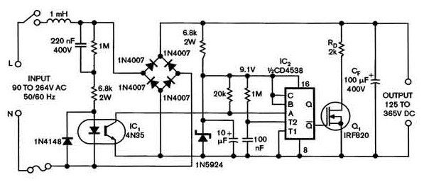
Universal power supply with a safe high-voltage capacitor power supply. Refer to that page to read the explanation about the related circuit diagram of the above power supply. The universal power supply circuit is designed to provide a stable output...
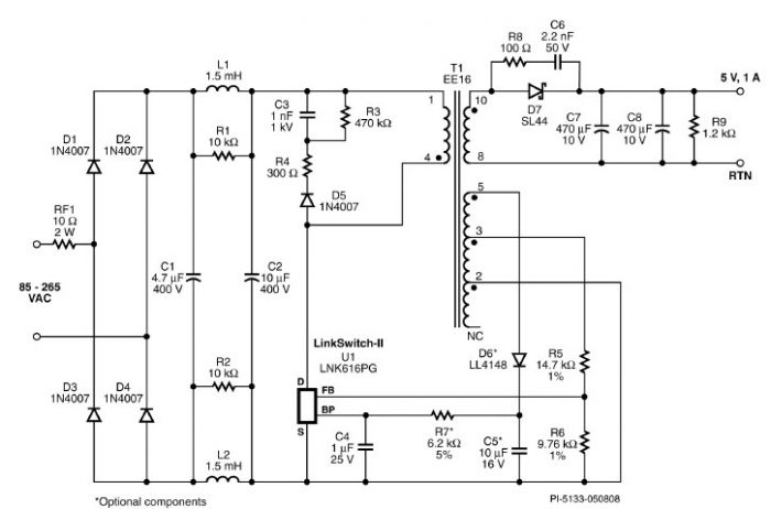
A very simple 5-volt constant voltage, constant current (CV/CC) universal-input power supply for cell phone or similar charger applications can be designed using the LNK616PG product from the LinkSwitch-II family. This low-cost charger adapter accepts a wide range of...

One of the drawbacks of a three-pin voltage regulator is that the input voltage needs to be 2.5 to 3 V higher than the output voltage. This makes these integrated regulators unsuitable for battery power supplies. For instance, if...

A power amp designed for use in low voltage, especially battery-operated, applications. For minimum parts count, C1 and C2 can be omitted. More: With pins 1 and 8 open circuit the gain in internally set to 20 dB. The described...
A keyed power input connector, series rectifier and a shunt rectifier, both 1N4007, prevent reverse voltage from being applied to the power input. A 27 volt metal oxide varistor clamps the voltage to the 78L05 that follow it, to...
Infrared remote control operates on 115 volts AC. This circuit enables the activation of any equipment that functions on 115 volts AC. The receiver circuit is based on the Radio Shack infrared system. The infrared remote control circuit designed for...