
Mains voltage bidirectional limit alarm protection circuit diagram

The circuit operates on the principle of voltage monitoring and protection. The input voltage is first reduced and stabilized to ensure the circuit functions reliably. The buck converter and voltage regulator work together to maintain a constant output voltage, which is crucial for the operation of the detection circuits. The overvoltage and undervoltage detection circuits (IC1A, IC1B, IC1C) are designed to respond quickly to fluctuations in the mains voltage, ensuring that any dangerous conditions are addressed immediately.
The relay (J) serves as the primary mechanism for disconnecting the power supply when an unsafe voltage level is detected. The use of transistors (VT) allows for rapid switching, which is essential for protecting sensitive electronic devices from damage due to voltage irregularities. The incorporation of piezoelectric ceramics for the alarm sound provides a reliable and loud indication of alarm conditions, ensuring that the user is alerted promptly.
The LED indicators (LED1 and LED2) provide a visual representation of the system's status. Their operation is directly tied to the outputs of the detection circuits, allowing users to easily determine whether the mains voltage is within safe limits. The design's compact nature allows for easy integration into various environments, making it suitable for both residential and commercial applications.
Overall, the circuit is designed for maximum efficiency and reliability, ensuring that it can effectively protect electrical devices from damage due to voltage fluctuations while providing clear alerts to users.When the alarm protection can be higher or lower than the predetermined value in the mains voltage, sound and light alarm, and automatically cut off the electrical power, electrical protection is not damaged. The device is small, full-featured, making simple and practical. Circuit shown in Figure 1. Mains voltage all the way from C3 Buck, DW regulator, VD6, VD7, C2 rectifier output stable 12V DC voltage supply circuit. Another route VD1 rectified, R1 buck, C1 filtered to produce about 10.5V voltage detection mains voltage variations in the input signal on RP1, RP2.
Door IC1A, IC1B composition overvoltage detection circuit, IC1C undervoltage detection, IC1D switching, IC1E, IC1F and YD piezoelectric ceramics composed audio pulse oscillator. VT transistors and other components and relay J circuit protection action. LED1 red for mains overvoltage indication LED2 green pipe for mains voltage indicator.Mains normal, non IC1A output high, IC1B, IC1C output low, LED1, LED2 are turned off does not emit light, VT cutoff, J does not operate, the normal electrical power supply, then point B is high, F4 output low, VD5 conduction, C point is low, audio pulse oscillator to stop, YD not sound.
When the mains overvoltage or undervoltage, IC1B, IC1C which has a high output, so point A goes high, VT saturated conduction, J pull power, disconnect the electrical power supply, the point B becomes low potential, IC1D output high, VD5 off, reverse resistance is large, the equivalent of an open circuit, audio pulse oscillator start-up, YD alarm will sound, and the corresponding light-emitting diode light indication. When debugging, using a power supply regulator, the voltage regulator is normal (220V), with an incandescent lamp as a load, make LED1, LED2 are off, incandescent light, and then the upper or lower limit on the regulator raised , adjust RP1 or RP2 make LED1 or LED2 just light, incandescent lamp off, the successful commissioning.All components can be installed in a small plastic box, will play two holes fixed LEDs on the lid, make a little hole larger fixed piezoelectric ceramics, and with an appropriate cap to the piezoelectric substrate was used as an aid tune to have loud chirping.
Related Circuits
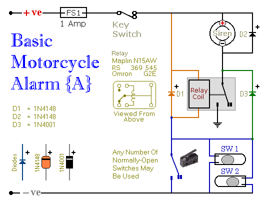
Relays can be utilized to protect motorcycles and have various other applications. When using relays with 6-volt coils, they provide security for "Classic Bikes." The alarms are compact, with completed boards occupying approximately half a cubic inch (8 cc)....

This circuit utilizes a programmable operational amplifier, specifically the HA2730, which is a two-amplifier monolithic chip featuring independent programming ports for each amplifier. The parameters of the amplifiers, including the slew rate, vary linearly based on a set current....
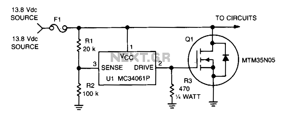
This circuit protects expensive portable equipment against all types of improper hookups and environmental hazards that could cause an overvoltage condition. It operates very quickly and does not latch up; rather, it recovers when the overvoltage condition is removed....

Fast charging circuit that illustrates voltage and current waveforms along with the configuration of the fast charge circuit for the charger. The detection and control circuit consists of three inverters (GMOS) from integrated circuits, enabling automatic control functions. The fast...
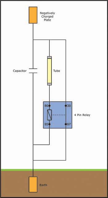
An individual has been studying Nikola Tesla's work for approximately 11 months and recently discovered Imhotep's concept of Radiant energy. The study of Nikola Tesla's contributions to electrical engineering and energy transmission has led to significant advancements in understanding electromagnetic...

The circuit utilizes an FET amplifier configuration for output, incorporating an NE5532 operational amplifier powered by a 15V supply. The output stage features a FET that amplifies the voltage after passing through several stages. The bias circuit for the...