
making a coolpix e990 dual USB / serial cable

To construct a combined dual serial and USB cable for the Nikon Coolpix 990 (e990) camera, it is essential to understand the pinout configurations for both the serial and USB connections. The process involves using a suitable cable that can accommodate both communication protocols, ensuring that the necessary wires are correctly connected to facilitate data transfer and power supply.
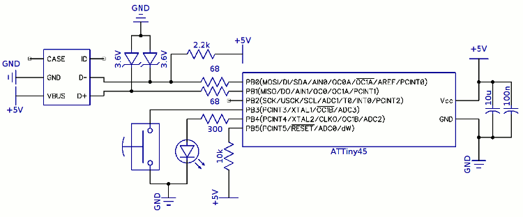
The dual cable design should incorporate a USB Type-A connector for connecting to a computer and a serial connector compatible with the Nikon Coolpix 990. The USB portion typically consists of four wires: red (VCC), black (GND), green (D+), and white (D-). The serial connection will require a standard 9-pin D-sub connector, where specific pins are designated for transmit (TX), receive (RX), and ground (GND).
To begin, obtain a USB cable and a serial cable, ensuring they are of appropriate gauge for the intended application. Strip the insulation from both cables to expose the individual wires. Next, identify the corresponding pins on the serial connector that will connect to the camera. The TX pin on the serial connector should connect to the RX pin on the camera, and the RX pin on the serial connector should connect to the TX pin on the camera. The ground connections must also be established between the camera and the serial connector.
For the USB connection, ensure that the VCC and GND wires are connected to the appropriate power pins on the serial connector, as needed. The D+ and D- wires should be connected to the corresponding pins on the serial connector that allow for data transmission.
After all connections are made, it is crucial to insulate the exposed wires to prevent short circuits. A heat-shrink tubing or electrical tape can be used for this purpose. Finally, test the combined cable with the Nikon Coolpix 990 to ensure that both serial and USB functionalities are operational. Proper testing will confirm that the camera can communicate effectively with a computer through both interfaces, enabling data transfer and device control.How to make a combined / dual serial and USB cable for the Nikon Coolpix 990 (e990) camera. 🔗 External reference
Related Circuits
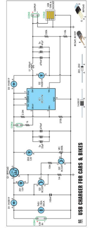
Seeking an efficient USB charger capable of operating from a 12V car battery? This unit operates at up to 89% efficiency and can charge USB devices effectively. This USB charger circuit is designed to convert a 12V car battery supply...
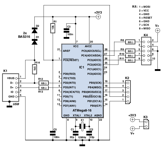
In the past, it was straightforward to utilize the parallel port of a standard PC to program various types of AVR microcontrollers. Currently, one must purchase a programmer that connects to the PC via USB, which increases the complexity...
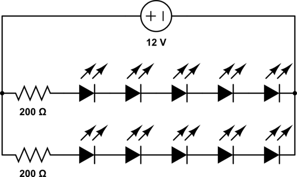
A 12V power supply is available, and there is a need to power LEDs with a forward voltage of 2V. It is questioned whether only six LEDs can be powered or if the cathode of one LED can be...
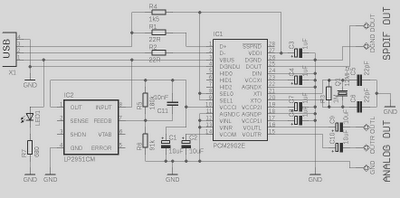
This is a high-quality preamplifier circuit with a built-in USB DAC designed for the Leachamp power amplifier. The schematic is derived from the PCM2902 datasheet. The circuit includes a DAC and ADC, SPDIF output and input, and an HID...
The project involves a trigger programming solution using a built-in pushbutton. The approach taken was to integrate a small USB keyboard circuit into the pen's interface. A proposed method for the pushbutton to trigger a programming command included adding...
In this circuit, the 7815 regulates the positive supply, and the 7915 regulates the negative supply. The transformer should have a primary rating of 240/220 volts for Europe, or 120 volts for North America. The centre tapped secondary coil...