
Making an Ikea Mood Lamp Beyond All Repair

The project involves a mood lamp controlled by an Arduino using RGB LEDs, providing customizable lighting effects. The RGB LEDs are arranged in a triangular configuration on a breadboard, with each LED connected to a TIP122 NPN transistor, allowing for higher current capability. The use of resistors is critical to prevent LED damage, with calculations based on the specific current requirements for each color. The circuit is designed to ensure that the total current provided is sufficient for the parallel arrangement of the LEDs.
The inclusion of RJ45 sockets facilitates modular connections, making it easier to manage wiring and maintain the project. The Arduino code employs PWM to control the brightness of each LED, creating a smooth transition between colors. The use of a simple cycling function allows for continuous color changes, enhancing the aesthetic appeal of the lamp. Future enhancements may include network control capabilities, enabling remote operation of the lighting effects.
In summary, this project demonstrates the integration of basic electronic components to create a functional and visually appealing mood lamp, while also providing a platform for further development and customization.Since I first got my Arduino and some RGB LEDs I`d wanted to build myself a mood lamp with some funky features (note that I used the word funky and not useful). Well, I`ve finally done it, and here is the blog post describing how. For this project I used the Ikea GrG¶nG¶, which was £4. 99 when I bought it. It quite a nice matt glass finish, which helps to diffuse light, and also it comes with the glass shade and the actual light fitting separate from one another (I put the light fitting to one side as I won`t be using it in this project). The brightnesses above were only chosen because they were the highest that were available at a fairly reasonable cost.
It might be better to match the brightnesses of all LEDs, although if memory serves, human eyes aren`t as sensitive to blue light as they are red and green, so it might be worth getting a brighter blue LED (I advise doing some more research). Firstly, LEDs tend to be highly directional (i. e most light goes in front of the led). There seem to be lots of diffusing and mixing lenses available at various shops, but I decided I`d have a go at just scuffing the LEDs with some sandpaper.
I was quite happy with the diffusion of light after having done that, so my next step was to breadboard the LEDs out. I arranged them into a triangular shape with a common ground rail on the breadboard, and individual positive rails for each diode.
Therefore resistors must be added to stop the components from being popped` (trust me, blown up LEDs stink). The required resistance can be easily calculated using Ohms Law V = IR. Although you can`t see it in that video, with only one LED of each colour it was far too hard to see when the surrounding light levels were high so I decided I`d add another led of each colour so they were arranged as in the following diagram.
I used three TIP122 NPN Transistors to allow the LEDs to draw more current than if I were just feeding them directly from the PWM outputs on the Arduino. The diagram below shows the circuit design as it was breadboarded out. This is in fact basically the same as the final circuit diagram (except with an Cat 5 patch cable separating the transistors from the resistors and LEDs).
Note the resistors and LEDs in parallel. Now that the LEDs are in parallel, the series part of the circuit must have twice the current required by the LEDs (Red: 100mA, Green and Blue 40mA). Therefore we require the following resistances. You could of course just go to the next resistor size up, but I like to make things complicated so I decided I`d try to get as close as I can with the resistors that I had at my disposal.
When combining resistors in parallel, the total resistance of the resistors in parallel is 1/R = 1/R1 + 1/R2 + + 1/Rn So, after breadboarding that and finding everything worked, I soldered everything to two breadboards. One containing the LEDs and Resistors, another containing the transistors and leads to connect to the arduino.
I also soldered some RJ45 sockets on to the boards, to allow me to connect the two components together over long distances (I could have used other means, but I have miles of patch cable lying around). Something to remember when soldering the RJ45 sockets is that if you don`t plan on using crossover cable, you should solder the two sockets in reverse to one another as in the diagram below.
Once you`ve done that, connect everything up and make sure everything works before glueing the LEDs to the bottom of your lamp. Then you`re pretty much done (except for coding the actual Arduino). The code I have so far is very simple, it simply fades between colours. const int led[] = {3, 5, 6}; const int delayTime = 10; #define RG 0 #define GB 1 #define BR 2 void setColour(const int * led, const int * colour) { for(int i = 0; i < 3; i +) { analogWrite(led[i], colour[i]); } } void cycle(int which, const int * led) { int a; int b; switch(which) { case RG: a = led[0]; b = led[1]; break; case GB: a = led[1]; b = led[2]; break; default: a = led[2]; b = led[0]; } for(int i = 0; i <= 255; i +) { analogWrite(b, i); analogWrite(a, 255 - i); delay(delayTime); } } void setup() { for(int i = 0; i < 3; i+) { pinMode(led[i], OUTPUT); } } void loop() { cycle(RG, led); cycle(GB, led); cycle(BR, led); } So there you have it.
I`m sure I`ve probably missed something out, so feel free to ask questions. My next step is to add some code that lets me change the light over the network, so keep checking back for more updates. 🔗 External reference
Related Circuits
Feed the cable through a hole in the chassis to the opposite side. There, between the fan and the rear panel, the IFD board can be installed upside down. Use a thin and flexible insulating material, such as PE...
Below is the main schematic of the RX + Xtall V9.0 SDR. The schematic has been divided into separate stages, each covered in its own page of build instructions on this website. Each shaded area can be clicked to...
This is an affordable buffer circuit designed for mixing passive pickups with EMG active pickups, or for buffering piezo pickups to be combined with magnetic pickups. The frequency response of the circuit is nearly flat, and the noise level...
This converter is useful when only the serial port on a personal computer is available, while the printer requires a parallel (Centronics) port. It converts a serial signal at 2400 baud into a parallel signal. The TxD line (pin...
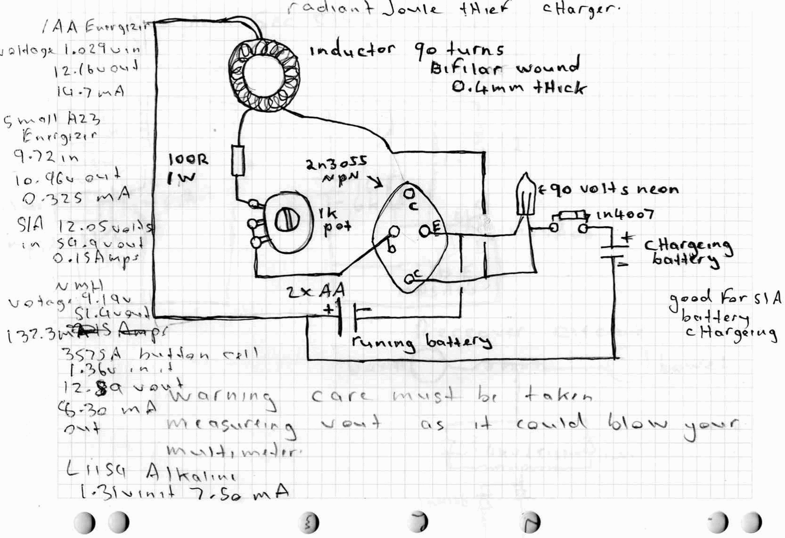
A high power joule thief circuit is explained in this post, which can be constructed by any new hobbyist. Here is the simplified drawing of the radiant joule thief battery charger. The inductor was wound with many turns until...
This project involves a USB interface for an alphanumeric LCD display, such as the 4x20 model, which can be controlled using the LCD Smartie program. The USB interface is implemented with the PIC18F2550 microcontroller and utilizes USB LCD modules....