
making multi function water level

The multi-function water level controller circuit is designed to automate the operation of a water pump based on the water level within a tank. The core of the circuit typically includes an integrated circuit (IC) that handles the logic and timing functions necessary for controlling the motor. The circuit features two level sensors, point A and point B, installed at predetermined heights inside the tank. Point A is positioned at the desired upper water level, while point B is at the bottom, ensuring continuous contact with water.
The operation begins when the water level rises and touches point A, sending a positive signal to point B. This signal resets pin #12 of the IC, which is responsible for controlling the relay that powers the motor. As a result, the relay is deactivated, and the motor stops running, preventing overflow or flooding.
To enhance safety, an automatic shutdown timer can be integrated into the circuit. This timer can be configured to monitor the operation of the motor. If the motor runs continuously for a specified duration (e.g., one hour), and the water level does not reach point A, the timer will trigger a shutdown of the motor, mitigating the risk of overheating.
Additionally, the circuit allows for manual control of the motor. Users can stop the motor at any time, enabling direct access to high-pressure water for tasks such as watering the lawn or washing vehicles. This can be achieved by implementing a stop logic connected to the base of transistor T1, allowing for instantaneous motor control.
The timing functionality of the circuit can be adjusted by varying the values of the timing components (P1 and C1), which dictate the duration of the motor operation before the automatic shutdown occurs.
To ensure uninterrupted operation during power outages, a backup power source, such as a 9-volt battery, can be incorporated. This battery remains disconnected from the circuit during normal operation but automatically engages when a power failure is detected. The diode D3 plays a crucial role in this mechanism, remaining high during normal power conditions to keep the battery inactive. Upon power loss, the cathode of D3 drops low, allowing the battery to provide power to the IC, thus maintaining continuity in the timing function without interruption.
Overall, this multi-function water level controller circuit offers a robust solution for managing water levels efficiently while incorporating safety features and user-friendly controls.The following multi-function water level controller circuit post is based on the suggestions expressed by Mr. Usman. Lets learn more about the requested modifications and the circuit details. 1) To protect the motor from potential overheating (or as a safety feature) can u add an automatic shutdown timer If the motor is running for one hour (or 1.
5hrs or 2-hrs) and the water level does NOT reach the level-sensor, the motor should be automatically stopped. Of course, it can be re-started manually by pushing the start button again. 2) Can the motor be manually stopped at any time For example, what if one wants to water the lawn (or wash the car) for a few minutes using high pressure water directly from the motor " So I guess, the STOP logic (1, 2 and 3) can be configured to the base of T1 (in your April 20 post) and it should work.
Pls comment, and if you have time maybe you can make a new post! 1)Water level reaches a pre-determined level: Point A and B may be appropriately fixed inside the tank for regulating this function. Since point B is situated at the bottom of the tank, remains connected with the water permanently, now as the level rises and comes in contact with point A, the positive potential from point A connects with point B, which instantly reset pin#12 of the IC, switching OFF the relay and the entire system.
2)A predetermined time has lapsed: This feature is already present in the below given circuit. The timing outputs can be increased to any desired extents simply by increasing the values of P1 and C1. 4) Powerfailure(load shedding): During a possible power failure or instantaneous power "blinks", the IC needs to be supplied with the required supply voltage so that the timing does not get interrupted.
This is very simply done by adding a 9 volt battery to the circuit. As long as normal power is present, the cathode of D3 stays high keeping the battery switched OFF from the circuit. The moment power fails, the cathode of D3 becomes low, providing a way-in to the battery power which smoothly replaces the supply to the IC without causing any "hiccup" to the counting operation of the IC.
🔗 External reference
Related Circuits
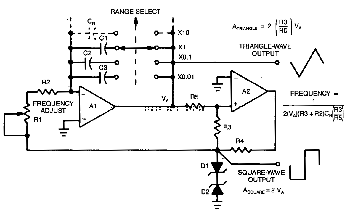
This circuit allows for continuous variation of the frequencies of the triangle and square waves produced, covering a full decade. When the resistance of RS is approximately equal to R3, the amplitudes of the two waveforms will be equal...
Simple triangle-wave generators have a limitation in that the waveform of their output signal typically cannot be modified. The circuit presented here makes... The described circuit addresses the inherent limitation of conventional triangle-wave generators by incorporating adjustable components that allow...
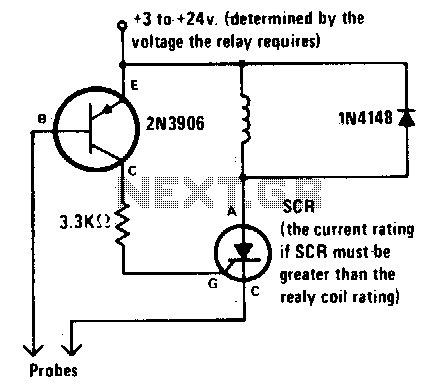
The alarm is activated when the liquid level rises above the probes and remains active even if the level subsequently drops below the probes. This latching mechanism provides an indication that the pre-set level has been reached or exceeded...
What exactly is a multivibrator? I suppose one definition would be 'a circuit which has several states'. This will do for now, it's quite loose so leaves plenty to the imagination! Conventional multivibrators have only two stages and come...
The K-type thermocouple is a commonly used temperature sensor in industrial production and scientific experiments. It can measure temperatures ranging from 0 to 1300 degrees Celsius in various applications, including direct measurements of gas, liquid, and solid surfaces. Its...

Hard water contains a high concentration of minerals, with calcium salts being the most problematic. However, a solution is available in the form of an inexpensive DIY project. To address the challenges posed by hard water, particularly the issues arising...