
MAX6953 Development board

The MAX6953 is designed to simplify the control of LED displays, making it suitable for applications that require efficient data handling and display management. The device operates via an I2C interface, allowing for easy communication with microcontrollers such as PIC or AVR. The integration of a 104-character ASCII table and the ability to define 24 custom characters enhance flexibility in display content.
The low-power shutdown mode is particularly useful in battery-powered applications, as it allows the system to conserve energy when the display is not in use. The synchronized segment blinking feature enables coordinated visual effects across multiple displays, enhancing the overall aesthetic of the application. The test mode is a critical feature for troubleshooting, as it allows all LEDs to be illuminated, making it easy to identify faulty components.
Brightness control is another vital aspect of the MAX6953. The 16-step digital brightness control feature allows for fine-tuning of the display's luminance, accommodating various ambient lighting conditions and user preferences. This capability ensures that the display remains visible and effective in different environments.
The addressing capability of the MAX6953 is a significant advantage, as it allows multiple drivers to be connected on a single I2C bus. By using just two pins (AD1 and AD0) to set a 4-bit address, it is possible to connect up to 16 individual MAX6953 drivers, enabling the creation of large-scale LED displays. This scalability makes the MAX6953 an excellent choice for projects ranging from simple displays to complex signage systems.
The availability of the MAX6953 in both 36-pin SSOP and 40-pin DIP packages provides flexibility in PCB design and integration, allowing designers to select the package that best fits their layout and assembly requirements. Overall, the MAX6953 is a versatile and powerful solution for driving LED displays in a wide range of electronic applications.The MAX6953 from Dallas Maxim is a compact cathode-row display driver that interfaces a microprocessor (like PIC or AVR) to four 5x7 dot matrix LED display trough an I2C compatible serial interface. The chip includes some features that can help us to handle easier the displaced data. These features are included on chip ASCII 104 character table and also fond data for 24 user definable characters, low-power shutdown mode, segment blinking that can be synchronized across multiple drivers if desired, test mode that forces all LEDs on (so that we can handle led problems) and also 16-Step digital brightness control that maybe differs from panel to panel.
In every MAX6953 we can set a 4 bit address via only two pins (AD1 and AD0) and with that way we can connect 16 drivers controlled from the same channel building huge LED displays. The chip is available in 36 pin SSOP and 40 pin DIP Packages 🔗 External reference
Related Circuits
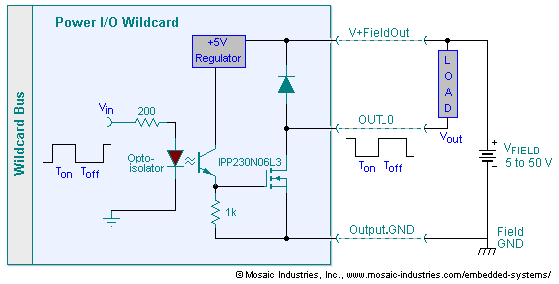
The embedded I/O board offers isolated high voltage switch inputs and eight high current, high voltage DC outputs. It utilizes optically isolated, open drain N-MOSFET transistors functioning as solid state relays (SSR) to control various resistive or inductive loads....
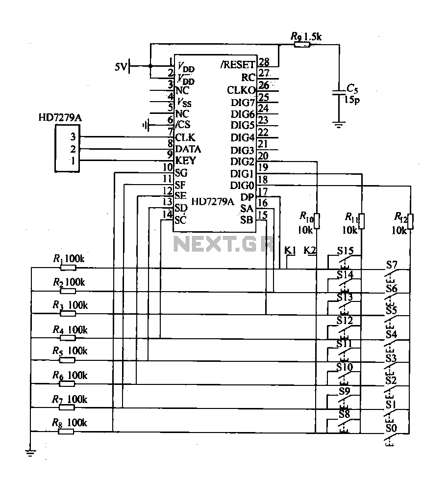
The design includes a front panel featuring buttons for setting 10 number keys (0-9), along with additional keys such as "Move Down," "Health," "Enter," "Recover," and a "Door Key," totaling 16 keys. The system also incorporates an interior door...
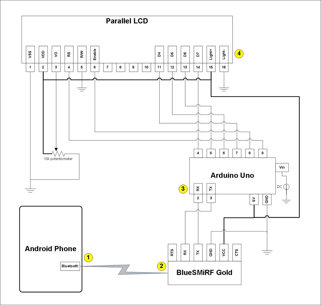
This project involves a modification of the Google Android sample app known as Bluetooth Chat, allowing users to type a message in the Android app and display that same message on an LCD connected to an Arduino Uno. The...
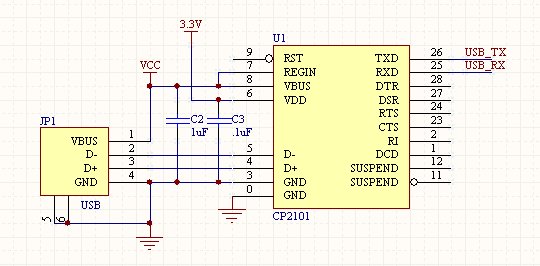
The CP210x USB ICs from Silicon Labs are commonly used in various applications. The CP2102 model provides a 3V TTL to a Virtual COM Port (VCP) over USB and generates the necessary 3.3V for the board. It is important...
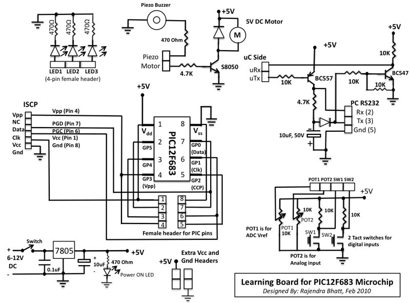
This microcontroller fascinated me a lot because I wanted to see what we can do with an 8-pin microcontroller (out of which 2 pins goes to power supply, so actually just 6-pins are left for I/O). So I thought...
BoardMaker3 is an integrated environment for the design of Printed circuit boards, offering a comprehensive set of tools that allow schematic entry, Spice simulation, 3D viewing and an Autorouter Interface. With a Customised graphics engine and a user configureable...