
Maximum Minimum Voltage Indicator

The circuit utilizes three operational amplifiers configured as voltage comparators to evaluate the input voltages at points A, B, and C. Each op-amp compares the voltage at its non-inverting input to the voltage at its inverting input, providing a binary output that indicates which input voltage is greater. The outputs of these comparators are connected to three LEDs, each representing one of the input voltages. The use of 1kΩ resistors in series with the LEDs ensures that the current flowing through the LEDs remains within safe limits, preventing potential damage due to excessive current.
In the configuration where the circuit indicates the highest voltage, the logic is such that only one LED will be illuminated at any given time, corresponding to the highest input voltage. For instance, if voltage A is the highest, LED A will light up, while the other two LEDs remain off. The operation of the circuit can be adjusted by altering the connections of the LEDs and diodes. When the diodes are reversed, the circuit switches to indicate the lowest voltage instead. This versatility allows for various applications depending on the specific requirements of the user.
Moreover, if the circuit is modified to include additional LEDs in place of the 1N4148 diodes, it can provide simultaneous indications for both the highest and lowest input voltages. This modification enhances the functionality of the circuit, making it suitable for applications where monitoring both extremes of voltage levels is essential. Overall, this circuit design is efficient and adaptable, making it a valuable tool in electronic applications that require voltage comparison and indication.This circuit indicates which of three voltages in the range from about about -4V to about +4V - at A, B and C - is the highest by lighting one of three indicator LEDs. Alternatively, it can be wired to indicate the lowest of three voltages or to indicate both the highest and lowest voltages.
Op amps IC1a, IC1b & IC1c are wired as comparators, whil e the three indicator LEDs and their series 1kO current limiting resistors are strung across the op amp outputs to implement the appropriate logic functions. For example, LED A will light only when pin 8 of IC1c is low (ie, A greater B) and pin 7 of IC1b is high (ie, A greater C).
Similarly, LED B will light only when pin 8 of IC1c is high (ie, B greater A) and pin 1 of IC1a is low (ie, B greater C). LED C works in similar fashion if the voltage at C is the highest. Note that if all the LEDs and their parallel 1N4148 diodes are reversed, the circuit will indicate the lowest of the three input voltages.
And if each 1N4148 diode is replaced by a LED, the circuit will indicate both the highest and lowest inputs. 🔗 External reference
Related Circuits
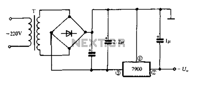
7900 series three-terminal fixed negative output voltage regulator circuit The 7900 series comprises a range of three-terminal fixed negative voltage regulators designed to provide stable output voltages. These regulators are specifically engineered to deliver a consistent output voltage, which is...

RS-232 Serial Interface Status Indicator Circuit. This circuit utilizes a single logic integrated circuit (IC) to indicate the transmission (TXD) and reception (RXD) statuses of a serial interface. The RS-232 Serial Interface Status Indicator Circuit is designed to provide visual...
The following diagram represents the schematic of an Active Tone Control circuit, commonly referred to as "ACTOR." The Active Tone Control circuit is an electronic audio circuit designed to enhance the loudness of audio signals by adjusting bass and...
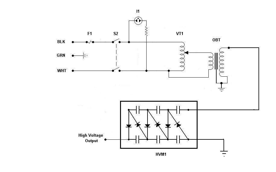
Using components from old microwave ovens, TV sets, and oil burners, it is possible to construct an economical instrument capable of producing high voltage outputs. The primary element in this setup is a voltage multiplier, which should be assembled...
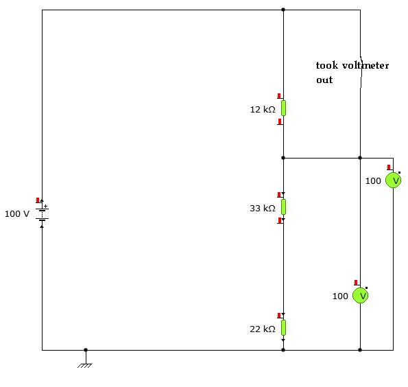
A user is utilizing YENKA software to diagram circuits but is experiencing confusion regarding the voltage calculations in a basic series circuit, as illustrated in the attached image. In a basic series circuit, components are connected end-to-end, forming a single...
Utilize a high-performance microcontroller (Piccolo TMS320F28035, 12-bit resolution, +/- 4 LSB offset, +/- 60 LSB gain) to measure the voltage across stacked battery cells and control related analog electronics for charge equalization. The microcontroller will also save data in...