
McCoy Mighty Midget Transmitter

The "Mighty Midget" transmitter circuit, characterized by its use of the 6GW8 triode-pentode, presents a unique amalgamation of oscillator and amplifier functionalities. The configuration is particularly noteworthy due to the inherent instability caused by the lack of neutralization, resulting in a design that behaves more like an oscillator than a traditional amplifier. The Colpitts oscillator, while popular due to its simplicity, introduces complexities when combined with the power amplifier stage, primarily due to the interaction between the tuned circuits. The RF choke's role in both the oscillator and amplifier circuits further complicates the design, as it can lead to unintended resonances and oscillatory behavior.
In practical applications, the design's sensitivity and instability can lead to unpredictable performance, particularly in terms of frequency stability and output power. The circuit's reliance on precise component values and tuning may limit its usability, especially for operators lacking advanced technical skills. The historical context of the design, including its evolution from earlier oscillator configurations and the attempts to address underdrive issues, highlights the challenges faced by engineers in achieving reliable RF amplification. The insights gained from operational testing, including the effects of varying anode voltage and the behavior of the circuit under different conditions, underscore the importance of thorough testing and modification before any practical deployment. Overall, while the "Mighty Midget" transmitter is an interesting study in oscillator-amplifier design, it serves as a cautionary example of the potential pitfalls in RF circuit design and the necessity for careful consideration of stability and performance factors.It uses a 6GW8 triode-pentode in an oscillator-amplifier design that combines a curious misapplication of oscillator fundamentals with insufficient attention paid to issues of amplifier stability. The result is a transmitter that shouldnot be duplicated and used on the air without considerable circuit modification.
Figure 1 ” Schematic of McCoy`s "Mighty Midget" transmitter. That the design`s power amplifier (6GW8 pentode) is not neutralized and includes operating-frequency-tuned circuits in its grid and plate circuits renders that stage a tuned-plate, tuned-grid oscillator that ”if you`re lucky ”locks to the the frequency of its triode crystal oscillator and stays there. The Mighty Midget`s troubles begin with its oscillator, a common-anode triode Colpitts circuit that nonetheless operates with its anode held above RF ground by the imprecisely resonant circuit formed by one RF choke (40 meters) or that RF choke plus another choke in series (80 meters) paralleled by the capacitance to ground of the triode anode and pentode grid and their interconnecting wiring.
The use of the Colpitts arrangement, the building-in of oscillator-anode parallel resonance, and the use of an RF choke in series with the power amplifier grid-leak resistor ”a usage more or less obsolete as of the mid-1950s ”suggest that in designing the Mighty Midget, McCoy had worked to avoid the power amplifier underdrive of the Boosted Pierce: Eleven years earlier, beginning on page 36 of October 1955 QST, he had modified an aperiodic-oscillator-based commercial design to overcome exactly that problem by adding oscillator-anode tuning and power-amplifier neutralization in "More Power with the AT-1. " The presence of oscillator anode (amplifier grid) resonance without the addition of amplifier neutralization results in a serious flaw: With its anode and grid tuned to roughly the same frequency by design, the transmitter`s high-gain pentode power amplifier is unstable to the point of acting more like a locked oscillator than just an amplifier.
Suspecting that this might be true with my version of the Mighty Midget after I encountered hysteresis in its amplifier plate tuning at 40 meters ”I couldn`t achieve the same output power peak, and maximum output occurred at different settings, when tuning through resonance from above and below resonance ”I disconnected the cold end of the oscillator cathode choke from the KEY jack and discovered that the Mighty Midget put out more RF power with its crystal oscillator disabled than with its crystal oscillator connected and operating! Adjusting the amplifier plate tuning across a wide range below, through, and above resonance and back again, I heard a series of grunts and squawks in my receiver as the final amplifier found and rejected varying modes of oscillation, some purer than others.
Holding my key down at the circuit`s highest power output setting, I discovered a relatively pure but highly frequency-unstable signal at about 7065 kHz. Moving a hand near the oscillator-anode chokes swung the frequency wildly. Keyed on and off, the amplifier-cum-oscillator chirped like the proverbial bird. This is a transmitter suitable for neither beginner nor Novice. Writing of his own experiences with the Mighty Midget, the PI4RAZ club website administrator ”who, if I have inferred from my drillings-down correctly, is Frank Waarsenburg, PA3CNO ”confirms the hazardous locked-oscillator nature of its design: When I increased the anode voltage to 300 V, the fight began.
David Newkirk was right. The tuned circuit in the anode of the triode is in the grid circuit of the pentode! I had actually built a crystal-oscillator-synchronized TPTG (tuned plate, tuned grid) oscillator. The transmitter put out more power with the crystal removed than with the crystal in place. (transl 🔗 External reference
Related Circuits
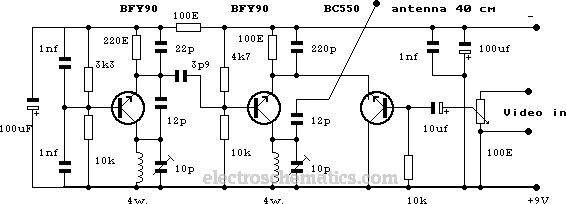
This compact video transmitter is highly effective for short-distance video surveillance, operating efficiently up to 100 meters. It can be paired with either a black-and-white or infrared camera module, providing excellent image quality on standard color or black-and-white televisions....
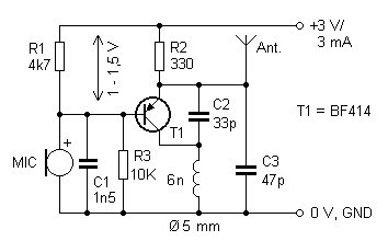
The presented FM transmitter circuit is constructed using BF414, BF324, or BF606 transistors. It features a 30 cm antenna that provides a range of approximately 30 meters indoors and even greater range outdoors. The power supply consists of two...
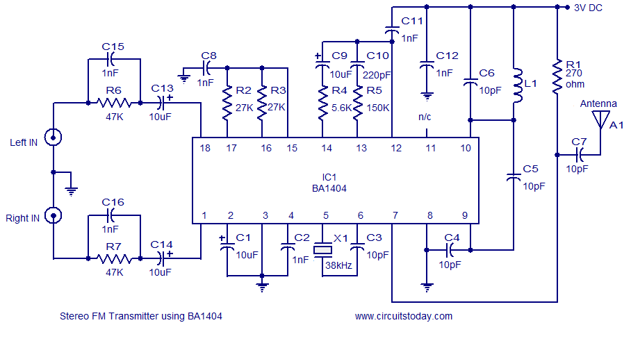
A high-quality stereo FM transmitter circuit is presented. This circuit utilizes the BA1404 integrated circuit from ROHM Semiconductors. The BA1404 is a monolithic FM stereo modulator that incorporates a stereo modulator, FM modulator, and RF amplifier circuitry. The FM...

The single-813 crystal oscillator transmitter, designed by RCA, was showcased in an advertisement on the back page of a 1938 "QST" magazine and published in the RCA HamTips bulletin, volume 1, number 4, dated December 1938. This transmitter delivers...

This small circuit transmitter processes audio signals from a sound table or microphone, as well as video signals from a camera, DVD, or video cassette. It has a composite video output, allowing direct transmission from a computer over a...

A simple TV transmitter circuit utilizing the TV modulator circuit IC MC1374. It operates with a 12V supply and is capable of broadcasting on channel 3 or 4, employing FM modulation for sound transmission. The TV transmitter circuit based on...