
Memory doorbell circuit

The described circuit functions as a visitor alert system that combines auditory and visual notifications. Upon pressing the doorbell switch K1, an electrical signal is generated, which activates the doorbell sound module. Simultaneously, LED D3 is illuminated, providing a visual cue that the doorbell has been activated.
In the event that no one answers the door, LED D3 continues to stay lit, serving as a reminder of the visitors who have come and left. This feature is particularly useful in scenarios where the homeowner may not have heard the doorbell.
The flip-flop circuit, composed of transistors T1 and T2, plays a crucial role in maintaining the state of LED D3. This configuration allows the LED to remain on even after the doorbell switch is released, effectively latching the state of the circuit until it is reset.
The half-wave rectification filter circuit, formed by diode D1 and capacitor C1, converts the AC voltage from the power supply into a usable DC voltage for the rest of the circuit. This ensures stable operation of the components, particularly the flip-flop and the LED, by smoothing out any fluctuations in the power supply.
Overall, this circuit design is efficient and serves a practical purpose in enhancing home security and visitor management, providing both sound and visual alerts to the homeowner.Pressed doorbell switch K1, the doorbell phonation, lighted up LED D3; if there are nobody to open the door, guests leave, D3 still on, this means there were guests came. Flip-flop is composed of T1, T2; D1, C1 form half wave rectification filter circuit, to support work voltage..
🔗 External reference
Related Circuits

This is a design circuit diagram of a moderate power FM transmitter circuit. The circuit operates using two transistors. It consists of a complete circuit diagram. The operation of this circuit is explained as follows: the voice signals picked...
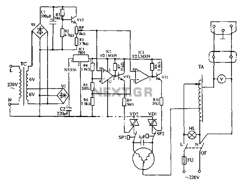
Automatic AC voltage regulator circuit The automatic AC voltage regulator circuit is designed to maintain a stable output voltage despite fluctuations in the input voltage. This circuit is essential for protecting sensitive electronic devices from voltage variations that can lead...
This is an LM338-based power supply that is uncomplicated and easy to construct. It has been in use for an extended period without any issues. The circuit lacks a current adjustment feature, which has been addressed by incorporating an...
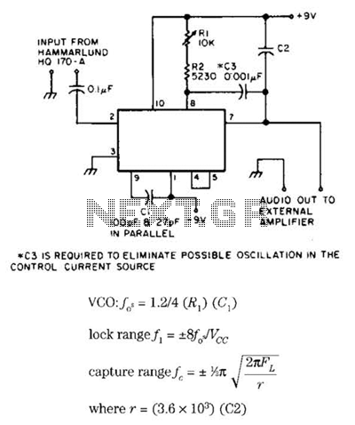
Useful for narrowband frequency modulation (NBFM) reception on older shortwave receivers that lack this capability, this circuit employs a phase-locked loop (PLL) integrated circuit, specifically the N565N. It was originally designed for use with an old Hammarlund HQ-170 receiver,...
This technique eliminates the need for an additional cable to power the FM antenna amplifier. The RF signal and the DC current that supplies the amplifier utilize the same cable simultaneously. An FM antenna booster circuit diagram can be...
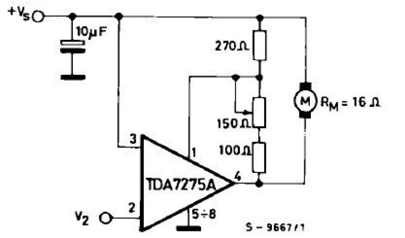
The TDA7275A linear integrated circuit, housed in a minidip plastic package, can be utilized to design a straightforward speed regulator electronic project suitable for regulating the speed of small DC motors. The TDA7275A DC speed controller project is specifically...