
Microcontroller measures heart rate through fingertip

The circuit begins with a photodiode that captures the reflected IR signals. The photodiode operates by generating a small current proportional to the intensity of the incoming IR light. This current is typically weak and requires amplification and conditioning to be useful for further processing.
The signal conditioning circuit includes a low-pass filter to eliminate high-frequency noise that may interfere with the desired signal. This filter can be implemented using passive components such as resistors and capacitors or through active components like operational amplifiers configured in a filter topology. Following the filtering stage, an amplifier circuit is employed to boost the signal to a suitable level for subsequent processing.
The amplifier may utilize a non-inverting configuration to ensure that the signal phase is maintained while providing the necessary gain. The gain can be adjusted by selecting appropriate resistor values in the feedback loop of the operational amplifier.
After amplification, the conditioned signal can be further processed by an analog-to-digital converter (ADC) if digital signal processing is required. This allows for the integration of the system with microcontrollers or digital signal processors, enabling advanced functionalities such as signal analysis, data logging, or real-time monitoring.
Overall, the design of the signal conditioning circuit is critical for ensuring accurate and reliable detection of the reflected IR signals, making it a vital component in various applications such as proximity sensing, object detection, and automated control systems.The reflected IR signal detected by the photo diode is fed to a signal conditioning circuit that filters the unwanted signals and boost the desired pu.. 🔗 External reference
Related Circuits
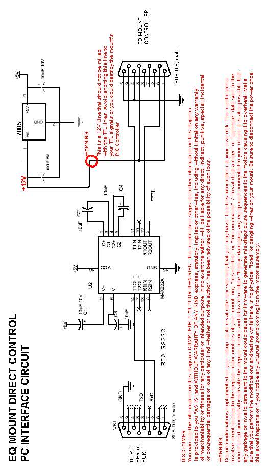
This page presents an alternative method to directly control the stepper motor board of your mount. The functionality for controlling the stepper motors remains largely unchanged from the original modification, as both methods allow commands to be sent from...
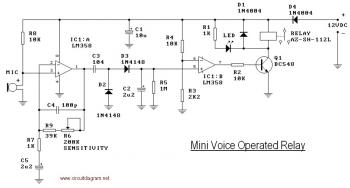
This circuit diagram illustrates a voice-operated relay, which functions similarly to a sound-activated switch circuit. It activates and deactivates the switch based on sound input. The output switch of this circuit is controlled by a relay. The release time...
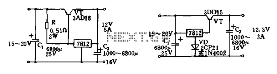
Expand integrated three-terminal regulator block circuit output current method The integrated three-terminal regulator is a versatile component commonly used in power supply circuits to provide a stable output voltage. This regulator typically consists of three terminals: input, output, and ground....
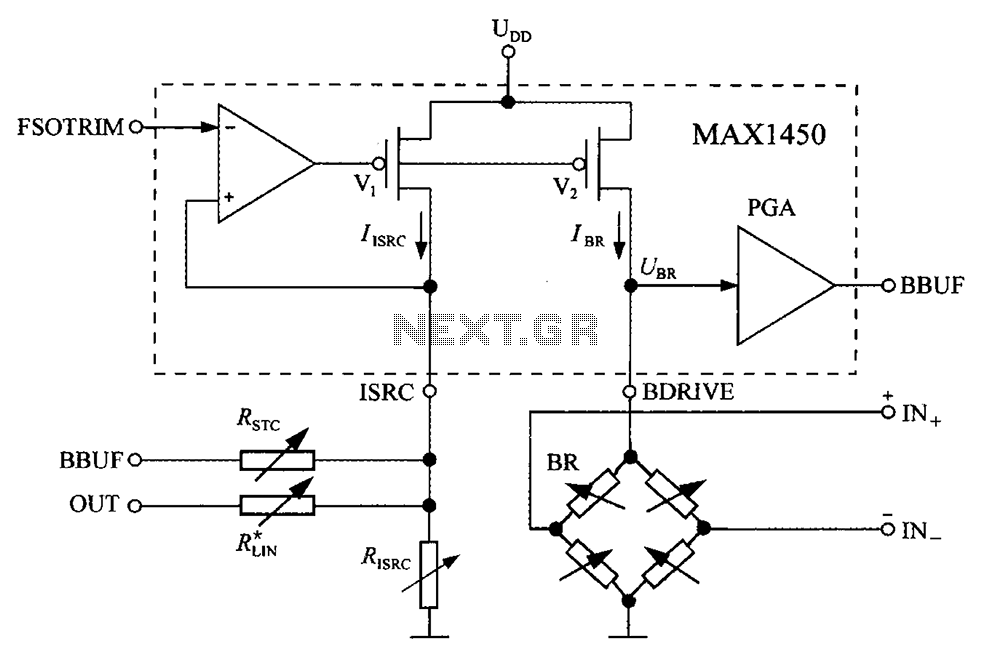
The circuit diagram for the bridge integrated pressure signal conditioner MAX1450 is composed of various components. The MAX1450 is a high-performance integrated circuit designed for signal conditioning in pressure sensing applications. It is particularly suited for use with resistive bridge...
INTRODUCTION It is essential to monitor the operation of nearly all automated and semi-automated devices, such as washing machines and autonomous systems. Monitoring the functionality of automated and semi-automated devices is crucial for ensuring optimal performance and reliability. This can...
The integrated circuit input side contains an oscillating circuit, where the oscillation frequency is determined by the external components L1, C1, and the sensor's equivalent capacitance. The equivalent capacitance increases as the sensor is immersed in liquid. The oscillating...