
Arduino DAC Signal Generator project

The triangular signal is a continuous time function that increases from a minimum width to a maximum width and then decreases at a constant rate. This waveform can be implemented using a loop that increments a variable until it reaches the maximum value (approximately 256) before decrementing back to zero. Once it reaches zero, the process repeats. The integer value of the variable is assigned to the PORTD register, converting the value to binary and providing a high (5V) output to the corresponding pins. For instance, if PORTD is set to 127 (binary 01111111), the first four pins (4-7) will output a high voltage, while the remaining four pins (0-3) will output a low voltage, resulting in a triangular waveform at the output.
The sine signal is more complex as it requires specific values at various points to accurately represent the waveform. An auxiliary table with 255 positions is utilized to store sine values ranging from 0 to 255. The procedure is similar to that of the triangular signal, but instead of using a variable for PORTD, the sine table values are employed, with the loop variable serving as an index to traverse the table.
The square pulse signal is straightforward to implement by alternating the output between 0 for one period and 255 for the next, continuously.
The sawtooth signal is akin to the triangular signal, with the distinction that it resets to zero upon reaching the maximum voltage level. This is achieved by incrementing a variable from 0 to 255, which is then assigned to the PORTD register, generating a sawtooth waveform at the output.
A digital-to-analog converter (DAC) is a circuit that receives a digital input and converts it into an analog voltage or current. This project employs a DAC to convert the values output to PORTD, which provides the sine and sawtooth signals. Each digital input corresponds to a specific analog output, with the circuit designed to handle 8-bit digital inputs (ranging from 0 to 255) and produce an output voltage of 0-5V.
Mathematically, for an 8-bit DAC to output 5V at 255 steps, each step corresponds to an output of 5/255 = 0.019V. Thus, the output voltage of a DAC can be calculated as the binary input multiplied by this step value. For example, an input of 129 (binary 10000001) would yield an output of 129 × 0.019 = 2.451V. The constructed circuit utilizes an 8-bit R-2R DAC, where each of the eight bits contributes to the resultant output voltage. If all bits are set to HIGH, the output approaches the reference voltage. Conversely, if the most significant bit is set to LOW, the output is halved. Generally, for an 8-bit DAC, the output voltage corresponds to the input value divided by 255 of the reference voltage.
The R-2R circuit consists of a network of resistors with two distinct values, where one resistor's value is double that of the other. In this implementation, 10kΩ and 20kΩ resistors are used. The digital data enters through 8 input lines (D0-D7) and is converted to the equivalent analog voltage (Vout) using the R-2R network. This principle underlies most DACs.
The circuit components include:
- 4 LEDs for signal indication
- 8 resistors of 5Ω (5% tolerance) for the R-2R circuit
- 8 resistors of 10kΩ (1% tolerance) for the R-2R circuit
- 2 potentiometers for frequency and duty-cycle adjustment
- 1 button for signal type selection
- 6 additional resistors of 10kΩ (1% tolerance)
- 20 cables for connections
- 1 raster circuit implementation
- 1 Arduino Uno board
- 1 oscilloscope for waveform visualization
The program is structured into three parts:
1. Declaration of global variables.
2. Setup function for initializing board settings and output variable values (e.g., sine table values).
3. Loop function that executes continuously while the main program runs.
The variables utilized include:
- `sine[254]`: A table of 255 positions holding sine values for output to the PORT register.
- `OutputArray[8]`: An array defining 8 outputs used for generating the four signals on pins D0-D7.
- `ledArray[4]`: An array for 4 outputs connected to LEDs that indicate the most active signal on pins D8-D11.
- `Signal`: A variable ranging from 0-4 that determines which signal case is executed.
- `buttonPin`: A variable indicating the pin connected to the signal change button (pin D12).
- `buttonState`: An input variable capturing the button's state (LOW when pressed, HIGH when not).
- `PotFunc`: A variable for the input potentiometer connected to pin A0 (analog input).
- `wave(value)`: A variable capturing the potentiometer's state.
- `PotGain`: A variable for the second potentiometer connected to pin A1 (analog input).
- `val1(value)`: A variable capturing the state of the second potentiometer.
The setup function initializes the Arduino pins and variables. Digital pins 0-11 are set as outputs, with pins 0-7 dedicated to circuit output, generating the desired sequence of bits for analog signal representation. Pins 8-11 control the LEDs indicating which signal is currently active. Digital pin 12 is configured as an input to read the button state, while analog pins 0 and 1 read values from the potentiometers that adjust signal intensity and frequency.
The loop function executes continuously, controlling the signal based on the button state. Initially, the signal is set to 0, resulting in no output. Pressing the button activates the first case, producing a triangular signal and illuminating the corresponding LED. The potentiometers are monitored for frequency and amplitude adjustments, and a delay function is implemented to allow for frequency changes in the signals. Each button press cycles through the available signals, with the program returning to the default state after all signals have been cycled through.Once the circuit gets current, all variables are initialized and the loop function is continually running. Initially all LEDs are off and there is no signal at the output. By pressing the signal switch, the first light that shows the most signal is at the output and the D0-D7 terminals give the appropriate signal which, when passing from the converter from digital to analog, outputs a triangular signal.
Of the 2 potentiometers (frequency setting potentiometer and amplitude adjusting potentiometer), we can adjust the frequency and width of the signal present in the output. If the toggle button is pressed again, the LED turns on indicating that the next signal-sine signal is active.
The D0-D7 terminals give a signal which, when passed from the digital to analog signal converter, will give us a sine signal. This is the case for the other two signals (square and sawtooth signals) with the only difference being the output and the respective LED that lights up each time.
Arduino has analog and digital pins, the problem is that while some of the signals requested are analog, the arduino can not output an analog signal but only digital. So the signals have to be done with the digital pin and go through a digital to analogue converter. In the present project the inverter is a resistor network R-2R which is extensively analyzed below.
Triangular signal
The triangular mathematical signal is a continuous function in time that starts from the average width increases to a maximum width and goes down to the bottom at a constant rate. This programming can be implemented with a loop that will increase a variable by 1 until the variable gets the maximum approximate value we have (256) and gives it to the output.
As soon as it reaches this value it will decrease until it reaches the minimum value that is 0.
Once it reaches 0 it starts to rise again and the process repeats continuously. The integer value of the variable loop is assigned to the PORTD register which converts the value to the binary and gives a high (5 volt) voltage to the corresponding pin outputs.
For example, if PORTD is set to 127 (11110000), then the first 4 pin (4-7) will be voltage while the other 4 (0 - 3) will be in low mode. So if this loop is running continuously at the output we have a triangular signal.
Sine signal
The sine signal is the most difficult of the four signals because it is not enough to have a variable that increases because the halftone has certain values at any moment.
Thus, a 255-position auxiliary panel is used which takes sine values in a range from 0 to 255, so that a signal approaching the sine signal is displayed at the output. After we have the value table, then the process is the same as the triangular signal, except that instead of PORTD taking the loop variable values, it takes the values of the table and the loop variable is used as a table of increase in the table.
Square pulse
Square pulse is very easy to implement as long as we give output 0 for one period and 255 for the next one continuously.
Saw signal
We could say that the saw signal is a triangular signal case since the only difference is that the saw signal after reaching the maximum voltage level instead of decreasing is zero.
This is done by using a loop for which continuously increases a i variable from 0 to 255 whose value is assigned to the PORTD register. So we have a saw signal at the exit.
DAC with R-2R grid
A circuit that receives a digital input and converts it to analog voltage or current is called a digital signal converter to an analogue.
Such a circuit was used in the present application to convert the values output to PORTD, which is an output port for the values of the sine signal and the sawtooth signal.

In such a system, each digital input corresponds to a certain analog output. It is a circuit that takes as a digital input 8 bit ie numbers from 0 (00000000) to 255 (11111111) and as output produces a voltage of 0-5V.
The mathematical explanation is quite simple: if we want an 8 bit DAC to output 5V at 255 execution steps each step will be 5/255 = 0.019V.
Thus the output voltage of such a DAC will equal the multipl

ication of the binary input on the pitch. Example for input number 129 (1000 0001) the output voltage would be 129X0.019 = 2.451V In the circuit that we constructed we made and used an 8-bit DAC R-2R.
This circuit is an 8 bit digital to analogue converter.
Each of the eight bits contributes to the resulting output voltage. If all 8 bits are in HIGH mode then the output is approximately equal to the reference voltage. If we change the most important bits in LOW mode then we will have about half of that trend. More specifically for a 8bit DAC if all 8 bit is HIGH then we get 255/256 reference voltage. If it becomes active, the most significant digit in LOW mode gives us 127/256 of reference voltages. Generally for every bit of X value between 0-255 the DAC will give X / 255 reference voltage.
Circuit R-2R
The digital data enters through 8 input lines (D0-D7) and adheres to convert to the equivalent analog voltage (Vout) on the R-2R network. Most DACs are based on this philosophy. The R-2R circuit is made of a set of resistors having 2 values. One is the double of the other. In the circuit that we implemented, we used resistors of 10KΩ and 20KOΩ. Below is the circuit implemented in Raster and its connection to the Arduino board.
Circuit Materials
- 4 LED for selected signal indication
- 8 Resistance 5ΩΩ (5% tolerance) Circuit R-2R
- 8 Resistance 10KΩ (1% tolerance) Circuit R-2R
- 2 Potentiometers for frequency and duty-cycle
- 1 Button for selecting signal type
- 6 Resistance 10KΩ (1% tolerance)
- 20 Cable for Connections
- 1 Raster Circuit implementation
- 1 Arduino Uno Implementation board
- 1 Oscilloscope for viewing the waveforms
Logic of the program

The program can be downloaded by clicking here and it consists of three parts and is as follows:
- 1.
Statement of global variables. - 2. Set-up function in which the program's default settings are related to the board and value output in the variables (example output values in the sine table).
- 3. Loop function in which, it is executed continuously for as long as the main program works.
The variables used:
- sine [254]: A table of 255 positions which takes sine values from 0 to 255.
It serves to output sine values to the PORT register. - OutputArray [8]: Table with 8 positions to be defined as outputs. These 8 outputs are used to give the 4 signals of the generator. Pins D0-D7
- ledArray [4]: Table 4 places defined as exits. They are connected with 4 LEDs that serve to show more signal there at the output each time. Pins D8-D11
- Signal: Variable which takes values from 0-4 and determines which case case will run each time.
- buttonPin: Variable which gets a value that is the location of the pin to which the button for signal change is connected.
Pin D12 - buttonState: Input variable, which takes the status of the button (LOW - pressed, HIGH - not pressed).
- PotFunc: Variable that gets a value (0 in our case) which is the input potentiometer of the potentiometer. Pin - A0 (Analog Input).
- wave (value): Variable which takes the value of the potentiometer state.
- PotGain: Variable that gets a value (1 in our case) which is the input potentiometer of the potentiometer.
Pin - A1 (Analog Input). - val1 (value): Variable which takes the value of the potentiometer status.
The Setup function
This function defines the functions of the Arduino boards Pin and initializes the variables. In particular, digital pin 0 to 11 is defined as outputs. Digital Pin 0-7 has to do with the output of the circuit and give us each time a sequence of bits that get states such that the analog signal (triangular, sine, square, saw) appears at the output.
Pin 8-11 gives output for the 4 leds that are used as signaling indicators for the most signal there is at the output each time.
Digital pin 12 is defined as input and gets a value from the toggle button. When the button is pressed then there is a 5V voltage in Pin, so it is in High state and when it is not pressed then there is no voltage and so it is in low mode.
Analog Pin 0 and 1 are defined as inputs that take values from the internal resistance of 2 potentiometers that regulate the intensity and frequency of the signals each time.

The Loop function
After the global variables are set and the setup function is executed, from the moment the loop function runs "continuously", in an endless loop for as long as the arduino is running or until it restarts. The code of this function is also the main program. The loop is initially run and one-case control of the signal function that gets the value from the toggle button.
Initially the signal is 0 and so nothing happens (default case status). If the button is pressed once, it enters the first case and the code begins to execute, which gives the output a triangular signal and illuminates the appropriate LED (active_led) signal.
At the same time the 2 potentiometers for frequency and amplitude changes are checked and with the map function we adjust the values we get from the potentiometers to the range we are interested in working on. Also with the delay function we define a delay in the loop so that we can change the frequency in the signals.
Along with all of this, the switching switch is controlled so that if the next case is pressed, the only one that changes is the output signal and the signal indicator light. The same happens every time you press the button until the signals are over and the program comes to the default state.
Related Circuits
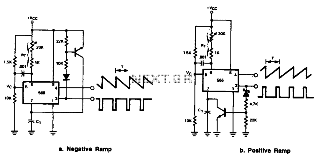
The 566 can be configured as either a positive or negative ramp generator. In the positive ramp generator configuration, the external transistor controlled by the output at Pin 3 quickly discharges capacitor C1 at the conclusion of the charging...
The core component of this DIY metal detector circuit is the CS209A integrated circuit (IC). The metal detector is constructed using a single 100µH coil, which has a diameter of 40 mm. The CS209A IC serves as the primary signal...

This liquid detector circuit diagram is designed using common electronic components. The liquid detector can activate an active buzzer to produce sound when a certain water level is reached. Since the water sensor and control circuit for the buzzer...
The drawings and photos below are for an operating incline railway that was built by the London Model Railroad Group for its O scale model railway club located at London, Ontario, Canada. This is a single car model loosely...
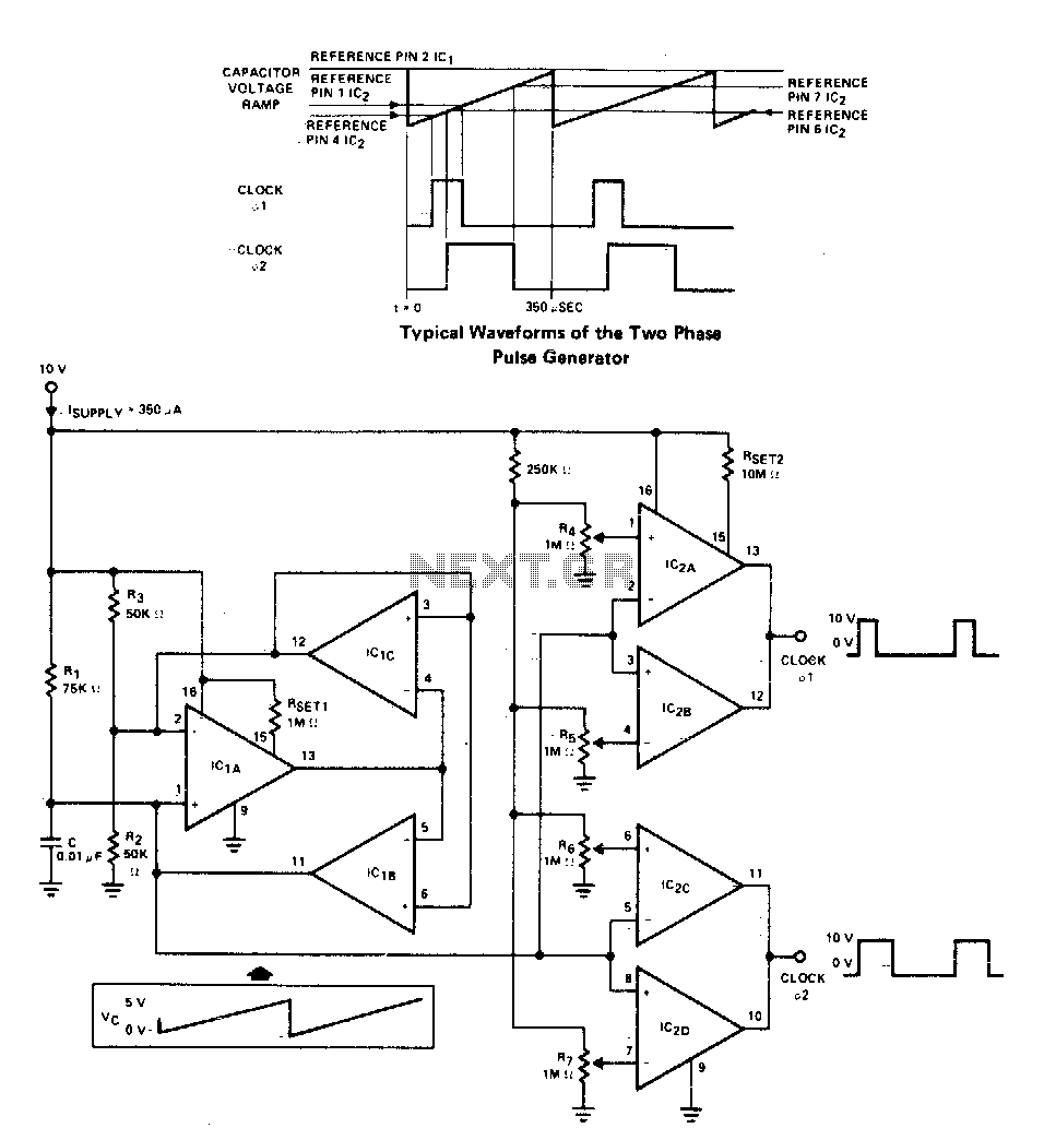
A two-phase clock generator utilizes two L161 integrated circuits to produce pulses with adjustable widths and phase relationships. Additionally, a ramp generator supplies input to two variable window comparators, which are configured using IC2A-IC2B and IC2C-IC2D, respectively. The two-phase clock...
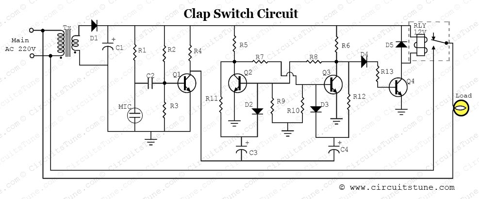
This is a simple electronic circuit for a clap switch project. It is suitable for beginner electronics learners who enjoy experimenting with new projects. The circuit can turn on or off a 220V electronic device, such as a fan...